UML 4+1 View
2010.04.11 14:40
4+1 Architectural View Model
From Wikipedia, the free encyclopedia
| This article needs additional citations for verification. Please help improve this article by adding reliable references. Unsourced material may be challenged and removed. (December 2008) |
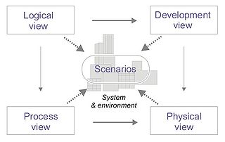
4+1 is a view model designed by Philippe Kruchten for "describing the architecture of software-intensive systems, based on the use of multiple, concurrent views".[1] The views are used to describe the system from the viewpoint of different stakeholders, such as end-users, developers and project managers. The four views of the model are logical, development, process and physical view. In addition selected use cases or scenarios are utilized to illustrate the architecture serving as the 'plus one' view. Hence the model contains 4+1 views: [1]
- Logical view : The logical view is concerned with the functionality that the system provides to end-users. UML Diagrams used to represent the logical view include Class diagram, Communication diagram, Sequence diagram [2].
- Development view : The development view illustrates a system from a programmer's perspective and is concerned with software management. This view is also known as the implementation view. It uses the UML Component diagram to describe system components. UML Diagrams used to represent the development view include the Package diagram [2].
- Process view : The process view deals with the dynamic aspects of the system, explains the system processes and how they communicate, and focuses on the runtime behavior of the system. The process view addresses concurrency, distribution, integrators, performance, and scalability, etc. UML Diagrams to represent process view include the Activity diagram[2].
- Physical view : The physical view depicts the system from a system engineer's point-of-view. It is concerned with the topology of software components on the physical layer, as well as communication between these components. This view is also known as the deployment view. UML Diagrams used to represent physical view include the Deployment diagram[2].
- Scenarios : The description of an architecture is illustrated using a small set of use cases, or scenarios which become a fifth view. The scenarios describe sequences of interactions between objects, and between processes. They are used to identify architectural elements and to illustrate and validate the architecture design. They also serve as a starting point for tests of an architecture prototype. UML Diagram(s) used to represent the scenario view include the Use case diagram[2].
본 웹사이트는 광고를 포함하고 있습니다.
광고 클릭에서 발생하는 수익금은 모두 웹사이트 서버의 유지 및 관리, 그리고 기술 콘텐츠 향상을 위해 쓰여집니다.
광고 클릭에서 발생하는 수익금은 모두 웹사이트 서버의 유지 및 관리, 그리고 기술 콘텐츠 향상을 위해 쓰여집니다.
댓글 0
| 번호 | 제목 | 글쓴이 | 날짜 | 조회 수 |
|---|---|---|---|---|
| » |
UML 4+1 View
| 가을의 곰을... | 2010.04.11 | 9187 |


