
This is a small tutorial introducing EMF and GMF plugins of Eclipse. EMF is the abbreviation of “Eclipse Modelling Framework”. Using EMF, models may be created and the java code for them is automatically created. Furthermore, EMF gives the possibility to generate code for an editor using the created model. This editor may be launched as an Eclipse application, which uses the defined model and gives the user the possibility to create model instances. GMF extends this functionality: Notation symbols may be matched to model types and associations. Based on the definition of notation symbols and the matching, java code for a graphic editor can be generated. Launching it as an eclipse application, the model instances can now be created as a diagram.
In this tutorial I will give a brief introduction, how to use EMF and GMF. The model will be a very basic business process model, which consists only of events and process steps. The goal will be to have a graphical editor, which may be used to create a business process using events and process steps. Basically this editor will be created without writing a single line of code.
Further reading: Here are the sources, which I used for creating the example. Further information about EMF, GMF and also Ecore can be found on the following pages:
- Project page of EMF
- EMF tutorial (GMF not included)
- Eclipse GMF tutorial
- Official Eclipse book on EMF (not free)
Getting started
First of all we need to use the Eclipse IDE. In the following example I am using the Juno distribution, but other distributions should do fine as well. Install the following plugins:
- EMF – Eclipse Modeling Framework SDK
- Graphical Modeling Framework (GMF) Runtime
- Graphical Modeling Framework (GMF) Tooling
- Graphical Modeling Framework (GMF) Tooling – Runtime Extensions
Creating the project using EMF and GMF
Creating a new project, choose “Other” and select “Empty EMF Project” in the “Eclipse Modeling Framework” folder.
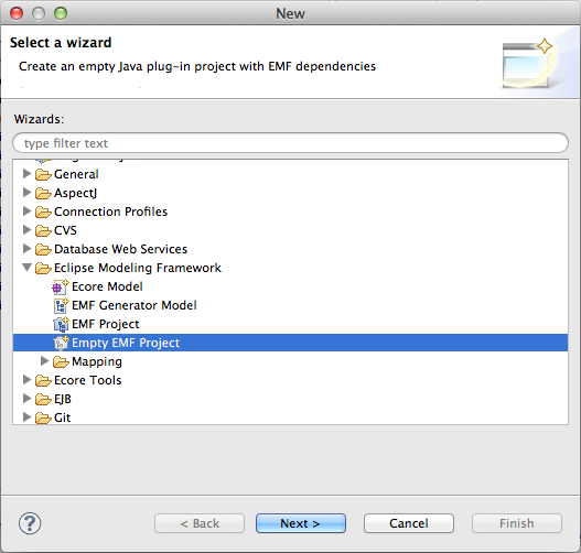
Add an empty EMF project
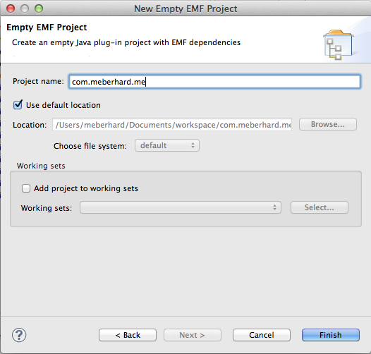
Choose a project name and click “Finish”.
Next step is to create an EMF Ecore model. The project, which we just created, contains a folder named “model”. Right-click this folder, and click “New” -> “Other”. Select “Ecore diagram” in the “Ecore Tools” folder.
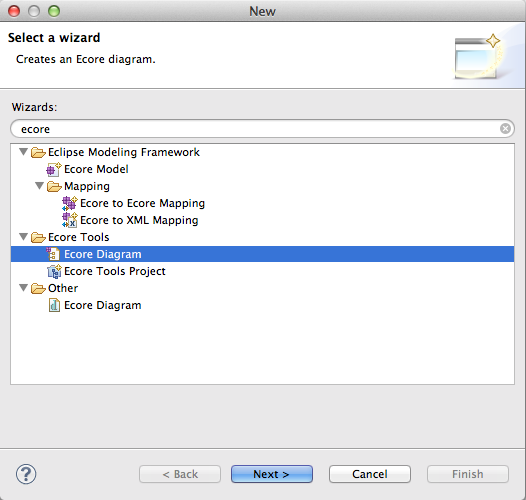
Add Ecore diagram
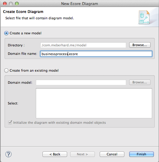
Choose a name, in this case “businessprocess.ecore.”
The model folder should now contain two files: “businessprocess.ecore” and “businessprocess.ecorediag”. On opening the ecorediag file an editor will show, which lets us create the model in a graphical environment.
Let’s create a basic EMF Ecore model, containing the class ProcessShape, which could either be a ProcessStep or an Event. ProcessShapes are connected using a Sequence. In order to create this model, we just need the types “EClass” and the connection “EReference” and “Inheritance”.
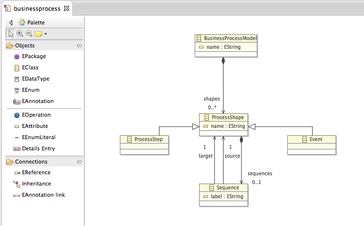
Create the EMF Ecore model for the business processes.
After saving, the model will be also updated in the .ecore file, wich should now look like this:
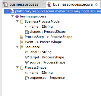
The update EMF .ecore model.
Right-click the model folder of the project, select “New” -> “Other” and choose “EMF Generator Model” in “Eclipse Modeling Framework”:
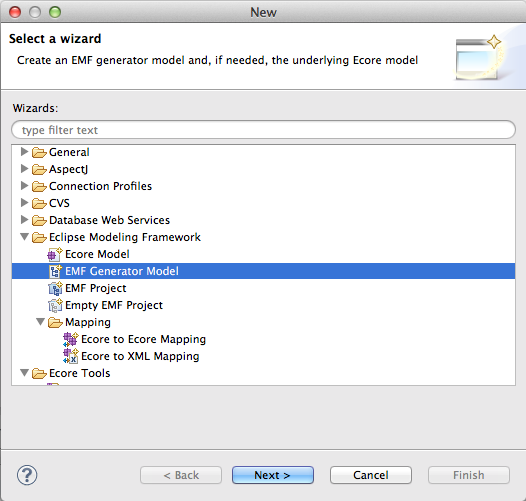
Add the EMF Generator model.
In the next step, be sure, that the model folder is selected and give a name for the EMF generator model, i.e. “businessprocess.genmodel”.
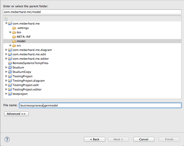
Select folder and name for the EMF generator model.
During the next step, we need to choose the model importer, select “Ecore model”.
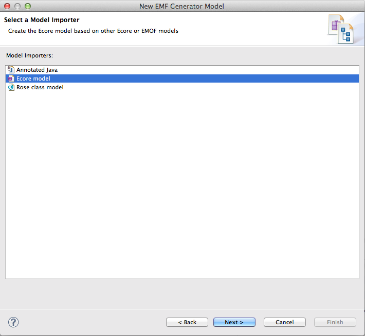
Select the model importer for the generator model.
After, we need to select the EMF .ecore model which we created. Click “Browse Workspace” and select “businessprocess.ecore” in the project we created:
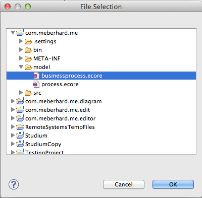
Select the ecore model for the generator model creation.
Now you just need to hit “Load”, go to the next step and click “Finish”. The file “businessprocess.genmodel” should now be created and reside in the “model” folder of the project. The .genmodel file will look similar to the .ecore file:

The genmodel file of the project.
We need to set the base package,select the first entity “Businessprocess” and open the Properties view. If it is not opened already, open it using right-click on “Businessprocess” and clicking “Show Properties View”. The basepackage needs to be set to the project name and the folder, in which the model resides. In my case, the name of the project is “com.meberhard.me” and the folder “model”, so the name of the base package is “com.meberhard.me.model”.
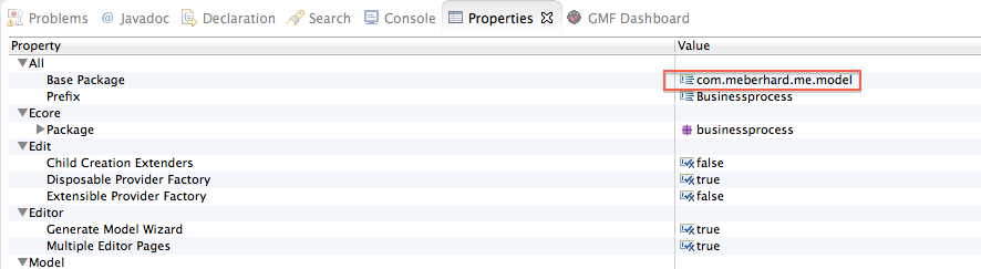
Properties view of the genmodel.
Now everything is set to generate the model and the edit code. Right click on top element “Businessprocess” in the .genmodel file and click “Generate Model Code”, do the same again and click “Generate Edit Code”.

Generate the model and the edit code.
If this step went well, you should now one new project in the workspace, ending on .edit, additionally the model code should be created in the “src” folder of your base project.
Now we may start with the graphical part, defining the notation symbols and map them to the model. In the eclipse menu, click on “Window” -> “Show View” -> “Other”. Select “GMF Dashboard” inside the “General” folder. The following view should open:
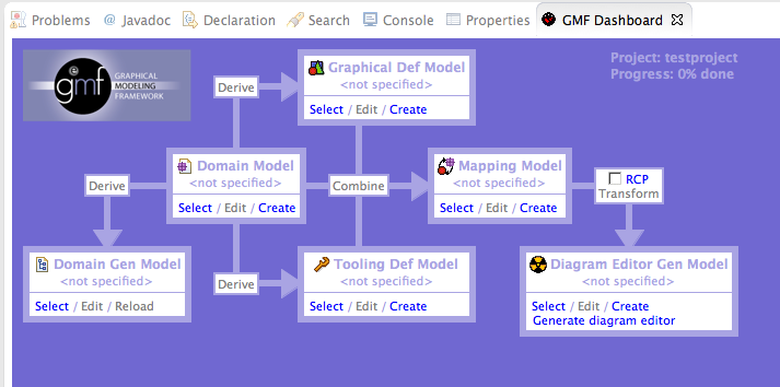
The GMF dashboard.
We start from “Domain Gen Model” – click on “Select” and choose the .genmodel file, which we created. After, click on “Select” in “Domain Model” and choose the EMF .ecore file, which we created. After that, click “Create” inside “Graphical Def Model”. Select again the “model” folder in the opening view and set the name to “businessprocess.gmfgraph”.
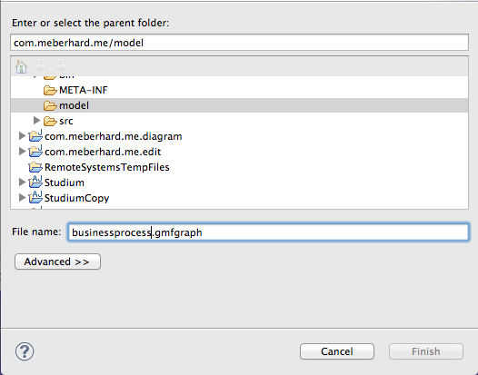
Creation of the GMFGraph model.
A new file will open, which contains an element in a list view, called “Canvas”. Right-click on “Canvas” and add a “Figure Gallery”:
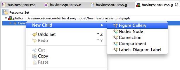
Adding a Figure Gallery in GMFGraph.
Right click the created “Figure Gallery” and add three times “Figure Descriptor”. Use the properties of the first one and give it the name “Rectangle”, use the properties of the second one and give it the name “Ellipse” and the properties of the last one to call it “Connection”. Right-Click the first “Figure Descriptor”, select “Add Child” and add the Rectangle. Right-Click the second “Figure Descriptor”, select “Add Child” and add the Ellipse. Right-click again the “Figure Gallery” and add a “Polyline Decoration”. Use the properties to call it “connection decoration”. Right-click the “Polyline Decoration” and add a “Polygon”. Right-click the “Figure Descriptor Connection” and add a “Polyline Connection”. Use the properties to set the name to “sequence” and the “Target Decoration” to “Polyline Decoration connection decoration”. After being successful, the .gmfgraph file should look like this:
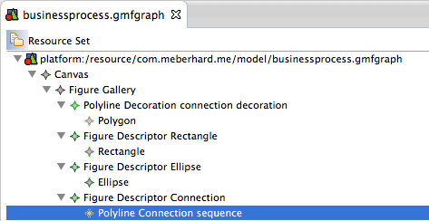
Updated gmfgpraph file, containing the Figure Gallery.
Right-Click again on the “Canvas” element and insert two children of the type “Node”. Use the properties of the first Node to give it the name “event”, in the dropdown next to “Figure” choose the “Figure Descriptor Rectangle”. Give the second Node the name “processStep” and choose the Figure “Figure Descriptor Ellipse”. This means, that events will be represented by Ellipses and processSteps by Rectangles.


Right-Click on “Canvas” and add a child “Connection”. Use the properties to give it the name “sequence” and set “Figure” to “Figure Descriptor Connection”. Use right-click on “Canvas” to add three times “Diagram Label”. Using the properties, the first Label should get the name “eventName”, the second label “processStepName” and the last label “sequenceLabel”. The GMFGraph model should now look like this:
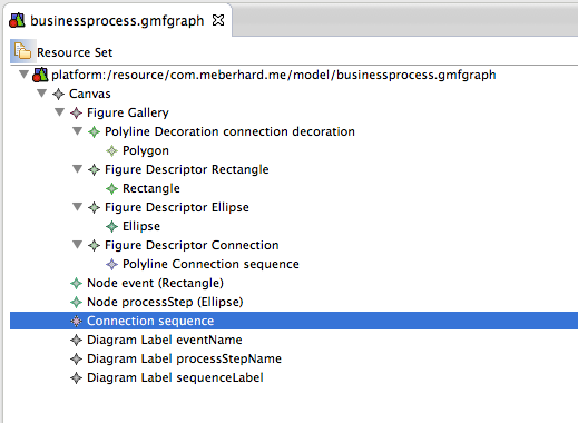
Complete GMFGprah model.
Going back to the GMF Dashboard, click on “Create” in “Tooling Def Model”. In the opening view, select the “model” folder and give it the name “businessprocess.gmftool”.
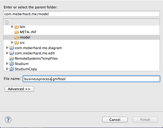
Creating the GMF tooling file.
The created file will already contain an element “Tool Registry” in a list view. Right-click the “Tool Registry” and add a child “Palette”. Right click the “Palette” and add three children “Creation Tool”. Use the properties, set the title of the first “Creation Tool” to “event”, the title of the second “Creation Tool” to “processStep” and the title of the third to “sequence”. The file should look like this:
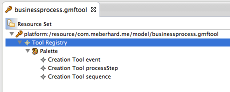
Creation of the GMF tooling file.
Right-Click the “model” folder of the project, select “New” -> “Other” and choose “Guide Mapping Model Creation” in the opening view, it is inside the folder “Graphical Modeling Framework”.
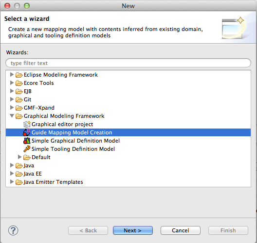
Add the Guide Mapping Model Creation to the model folder of the project.
Make sure, that the folder “model” is selected and choose the name “Creation of the GMF tooling file”.
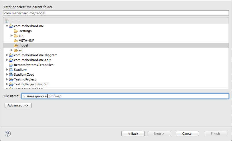
Adding the file gmfmap to the project.
Leave the next view like it his and click “Next”, the view should look like this:
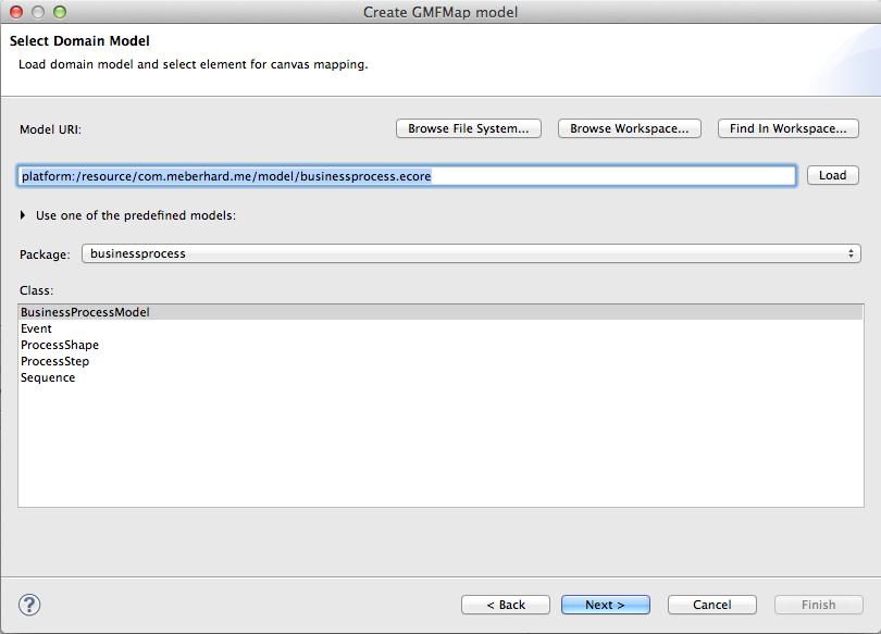
The Select Domain Model model view while creating the GMFMap model.
Leave the following two views also like they are. The last view shows the mapping and should look like this:
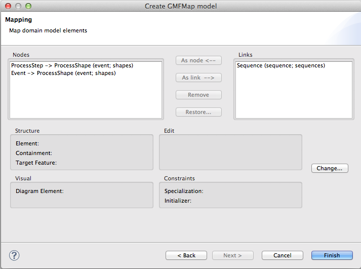
The mapping when creating the GMFMap file.
Click on the right side on “Sequence (sequence; sequences)” and click the button “Change”. Set the “Source Feature” to “EReference source” in the opening dialogue.

Set the source feature to ERference source.
Click “Finish” to create the file and open it. We need to make some manual amendments, i.e. adding the labels and fixing the mapping from processStep to Ellipse (because now both event and processStep are assigned to Rectangle).
Choose the mapping, which contains “Top Node Reference <shapes:ProcessStep/event>”. Open all children and open the properties of “Node Mapping <ProcessStep/event>”.
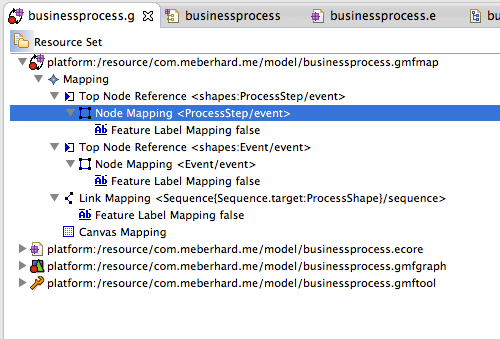
Altering the properties of the GMFMap model.
In the properties, change “Diagram Node” from “Node event (Rectangle)” to “Node processStep (Ellipse)”.
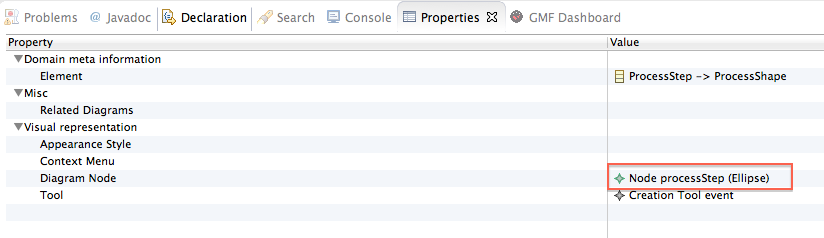
Altering mapping properties.
After, select the “Feature Label” of the three mappings and assign the processStepName label to the processStep, the eventName label to the event and the sequenceLabel to the sequence.
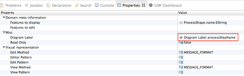
Example of the Diagram Label assignment.
After this is done, right click on the first element of the list and click on “Create generator model”.
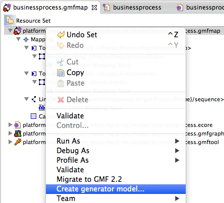
Create the generator model.
In the following view, be sure that the “model” folder is selected and choose the name “businessprocess.gmfgen”.
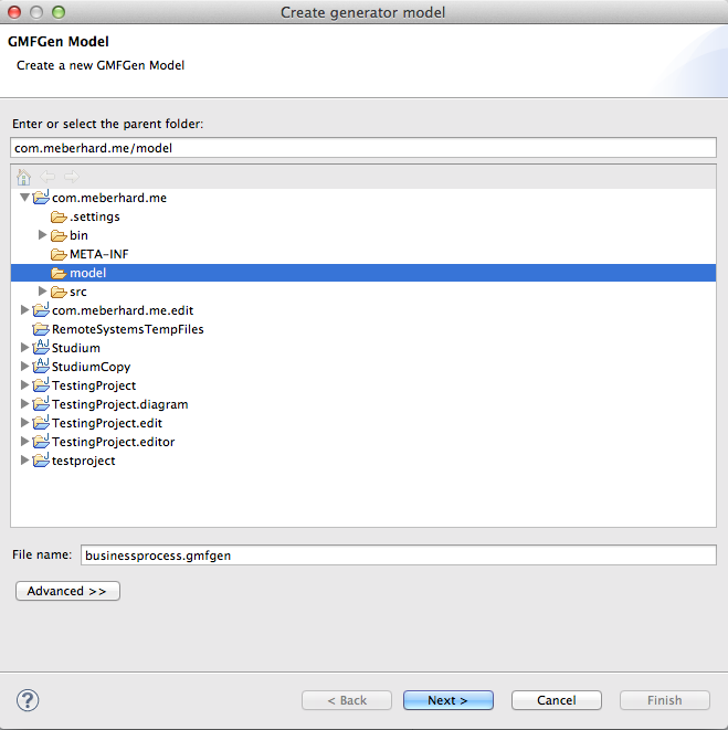
Create the generator model.
Don’t change nothing in the following views, click next until you are able to click Finish. After clicking “Finish”, the file “businessprocess.gmfgen” should be available in the “model” folder. Open the file, right-click the first element and click “Generate Diagram Code”.
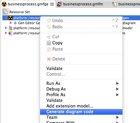
Generate the diagram code from the gmfgen file.
Your workspace should now contain a new project ending in “.diagram”. Right-click the project and click on “Run as” and choose “Eclipse application”.

Run the .diagram project as eclipse application.
After the new eclipse instance opened, click the “New” icon and search for “Businessprocess Diagram” in the “Examples” folder.
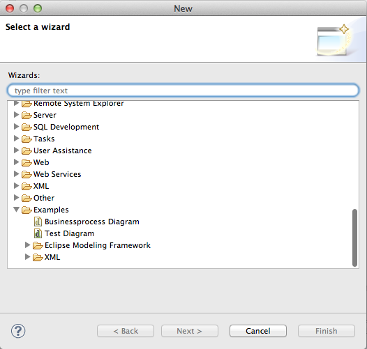
Add a new businessprocess diagram.
Now you are able to create a very basic process diagram, which consists of events and processSteps. You can use “sequence” in the “palette” to connect single symbols.


