[C# Apps] Editor3D: A Windows.Forms Render Control with interactive 3D Editor in C# Editor3D: C#의 대화형 3D 편집기가 포함된 Windows.Forms 렌더 컨트롤

Editor3D: A Windows.Forms Render Control with interactive 3D Editor in C#

 
2 Sep 2023CPOL9 min read
An easy to use 3D control which can be integrated into an application in a few minutes
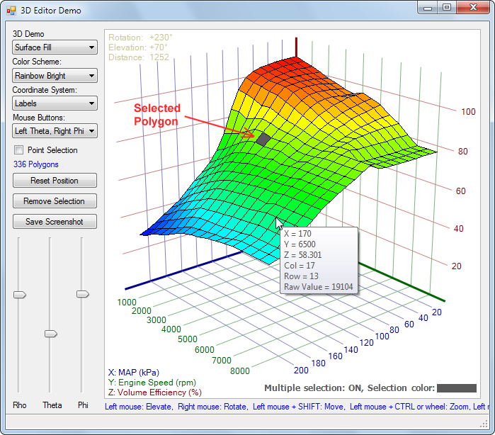
A universal ready-to-use interactive 3D Editor control for System.Windows.Forms applications. It displays 3D data that the user can modify with the mouse. The control consists of a single C# file and is optimized for maximum speed.
System.Windows.Forms 3D Editor Control in C#

Features

  • NEW: The control has been completely rewritten (4100 lines of code, 170 kB filesize!)
  • NEW: The user can select 3D objects with the mouse while pressing the ALT key.
  • NEW: The user can move points or objects with the mouse in the 3D space.
  • NEW: A callback provides full control over user actions and object selection.
  • NEW: 3D objects can be added, modified and removed on the fly.
  • NEW: A new demo "Animation" shows how to dynamically change properties of 3D objects.
  • NEW: The border color changes when the 3D editor gets the keyboard focus
  • NEW: Line width and scatter point size are adapted when zooming
  • NEW: Can be configured to use only the left or middle mouse button for all movements
  • Support for drawing 3D objects. Added example "Pyramid" and "Sphere"
  • Rendering speed optimized to the extreme
  • BUGFIX: Sometimes the Z axis was drawn on top of the 3D object instead behind
  • Display a tooltip when the mouse is over a 3D point
  • Resizing of 3D object when resizing 3D control
  • Completely rewritten to allow display of multiple graphs at the same time
  • Individual color scheme for each graph
  • Surface plots can also be drawn as grid
  • User messages can be drawn into the control
  • Added scatter squares and triangles
  • Copy Screenshot to Image
  • Set Rho, Theta, Phi programmatically
  • Drawing of scatterplots
  • Coordinate system now also with negative values
  • Universal ready-to-use 3D Graph control for System.Windows.Forms applications
  • Derived from UserControl
  • Target: Framework 4 (Visual Studio 2010 or higher)
  • Display of 3 dimensional functions or binary data (X, Y, Z values)
  • Very clean and reusable code written by an experienced programmer
  • All code is in one single C# file with < 1200 lines
  • Optional function compiler allows to enter formulas as strings
  • Optional coordinate system with raster lines and labels
  • Optionally multiple color schemes
  • The user can rotate, elevate and zoom with the mouse or with 3 optional TrackBars
  • Zooming is also possible with the mouse wheel, but only if the 3D Graph has the focus.
  • The entire code is optimized for the maximum speed that is possible.
  • An optional legend displays the current rotation angles to the user in the top left corner.
  • An optional legend displays a user defined text for the axis in the bottom left corner.
  • The black lines between the polygons can be turned off.
  • Automatic normalization of 3D input data with 3 options

Why this Project?

I'am writing an ECU tunig software HUD ECU Hacker for which I need a 3D Viewer which displays the calibration tables.
I searched a ready-to-use 3D Control in internet but could not find what fits my needs.
Huge 3D software projects like Helix Toolkit are completely overbloated (220 MB) for my small project.
Commercial 3D software from 0 USD up to 00 USD is also not an option.


WPF 3D Chart (from Jianzhong Zhang)

I found WPF 3D Chart on Codeproject.

It is very fast because WPF uses hardware acceleration.
The graphics processor can render 3D surfaces which must be composed of triangles.
But it is difficult to render lines. Each line would have to be defined as 2 triangles.
I need lines for the coordinate system.
I also need lines which display discrete values on the 3D surface.
I want each value in a data table to be represented as a polygon on the 3D object.
The screenshot at the top shows the representation of a data table with 22 rows and 17 columns.
I found it too complicated to implement this in WPF.
Extra work must be done to integrate a WPF control into a Windows.Forms application. See this article.

Plot 3D (from Michal Brylka)

Then I found Plot 3D on Codeproject.
This is more what I'am looking for but the code is not reusable and has many issues.

It is one of these many projects on Codeproject or Github which the author never has finished, which are buggy and lack functionality.
There is no useful way to rotate the 3D object. Instead of specifying a rotation angle you must specify the 3D observer coordinates which is a complete misdesign.
After fixing this I found that rotation results in ugly drawing artifacts at certain angles.
The reason is that the polygons are not rendered in the correct order.
The code has a bad performance because of wrong programming. For example in OnPaint() he creates each time 100 brushes and disposes them afterwards.
The code has been designed only for formulas but assigning fix values from a data table is not possible.

Editor3D (from Elmü)

I ended up rewriting Plot 3D from the scratch, bug fixing and adding a lot of missing functionality.
The result is a UserControl which you can copy unchanged into your project and which you get working in a few minutes.
The features of my control are already listed above.
As my code does not use hardware acceleration the number of polygons that you display determines the drawing speed.
Without problem you can rotate and elevate the 3D objects of the demos in real time with the mouse without any delay.
However if you want to render far more polygons it will be obviously slower.
For my purpose I need less than 2000 polygons which allows real time rotating with the mouse.
Download the ZIP file and then run the already compiled EXE file and play around with it and you will see the speed.

Demo: Surface Fill
System.Windows.Forms 3D Editor Control in C#

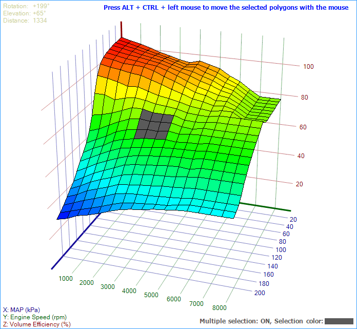
Here you see data from a table with 22x17 values displayed as 3D surface with coordinate system.

 
int[,] s32_Values = new int[,]
{
    { 9059,   9634, 10617, 11141, ....., 15368, 15368, 15368, 15368, 15368 }, // row 1
    { 9684,  10387, 11141, 11796, ....., 15794, 15794, 15794, 15794, 15794 }, // row 2
    .........
    { 34669, 34210, 33653, 33096, ....., 27886, 26492, 25167, 25167, 25167 }, // row 21
    { 34767, 34210, 33718, 33096, ....., 27984, 26492, 25167, 25167, 25167 }  // row 22
};

int s32_Cols = s32_Values.GetLength(0);
int s32_Rows = s32_Values.GetLength(1);

cColorScheme i_Scheme = new cColorScheme(me_ColorScheme);
cSurfaceData i_Data   = new cSurfaceData(e_Mode, s32_Cols, s32_Rows, Pens.Black, i_Scheme);

for (int C=0; C<i_Data.Cols; C++)
{
    for (int R=0; R<i_Data.Rows; R++)
    {
        int s32_RawValue = s32_Values[C,R];

        double d_X = C *  10.0;
        double d_Y = R * 500.0;
        double d_Z = s32_RawValue / 327.68;

        String s_Tooltip = String.Format("Col = {0}\nRow = {1}\nRaw Value = {2}", 
                                         C, R, s32_RawValue);
        cPoint3D i_Point = new cPoint3D(d_X, d_Y, d_Z, s_Tooltip, s32_RawValue);

        i_Data.SetPointAt(C, R, i_Point);
    }
}

editor3D.Clear();
editor3D.Normalize = eNormalize.Separate;
editor3D.SetAxisLegends("MAP (kPa)", "Engine Speed (rpm)", "Volume Efficiency (%)");
editor3D.AddRenderData(i_Data);

editor3D.Selection.Callback       = OnSelectEvent;
editor3D.Selection.HighlightColor = Color.FromArgb(90, 90, 90); // gray
editor3D.Selection.MultiSelect    = true;
editor3D.Selection.Enabled        = true;
editor3D.Recalculate(true);


When you use discrete values for X,Y and Z which are not related like in this example make sure that X,Y and Z values are normalized separately by using the parameter eNormalize.Separate because the axes have different ranges.

Each point in the grid has a tooltip assigned which shows the values X,Y,Z, Row, Column and Raw value.

This demo allows user selection of multiple polygons or points in the grid while pressing the ALT key.
The Z-values of the selected points can then be modified with the mouse while pressing ALT + CTRL.
The selection and movement are handled in a user defined callbackOnSelectEvent().

Demo: Math Callback

System.Windows.Forms 3D Editor Control in C#

Or you can write a C# callback function which calculates the Z values from the given X and Y values.

 
cColorScheme i_Scheme = new cColorScheme(me_ColorScheme);
cSurfaceData i_Data   = new cSurfaceData(ePolygonMode.Fill, 49, 33, Pens.Black, i_Scheme);

delRendererFunction f_Callback = delegate(double X, double Y)
{
    double r = 0.15 * Math.Sqrt(X * X + Y * Y);
    if (r < 1e-10) return 120;
    else           return 120 * Math.Sin(r) / r;
};

i_Data.ExecuteFunction(f_Callback, new PointF(-120, -80), new PointF(120, 80));

editor3D.Clear();
editor3D.Normalize = eNormalize.MaintainXYZ;
editor3D.AddRenderData(i_Data);
editor3D.Recalculate(true);

A modulated sinus function is displayed on the X axis from -120 to +120 and on the Y axis from -80 to +80.
The 49 columns and 33 rows of points result in 48 columns and 32 rows of polygons (totally 1536).

When you use functions make sure that the relation between X,Y and Z values is not distorted by using the parameter eNormalize.MaintainXYZ.


Demo: Math Formula
System.Windows.Forms 3D Editor Control in C#

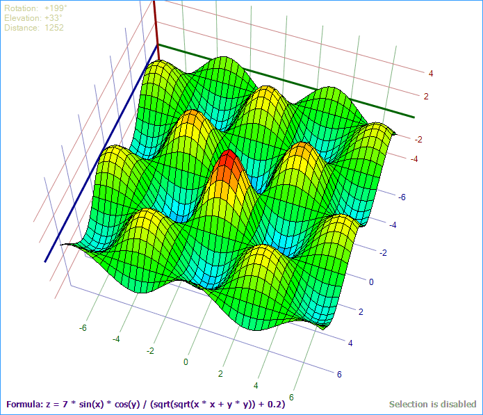
Or you can let the user enter a string formula which will be compiled at run time:

 
cColorScheme i_Scheme = new cColorScheme(me_ColorScheme);
cSurfaceData i_Data   = new cSurfaceData(ePolygonMode.Fill, 41, 41, Pens.Black, i_Scheme);

String s_Formula = "7 * sin(x) * cos(y) / (sqrt(sqrt(x * x + y * y)) + 0.2)";
delRendererFunction f_Function = FunctionCompiler.Compile(s_Formula);
i_Data.ExecuteFunction(f_Function, new PointF(-7, -7), new PointF(7, 7));

editor3D.Clear();
editor3D.Normalize = eNormalize.MaintainXYZ;
editor3D.AddRenderData(i_Data);
editor3D.Recalculate(true);


Demo: Scatter Plot
System.Windows.Forms 3D Editor Control in C#


cColorScheme i_Scheme = new cColorScheme(me_ColorScheme);
cScatterData i_Data   = new cScatterData(i_Scheme);

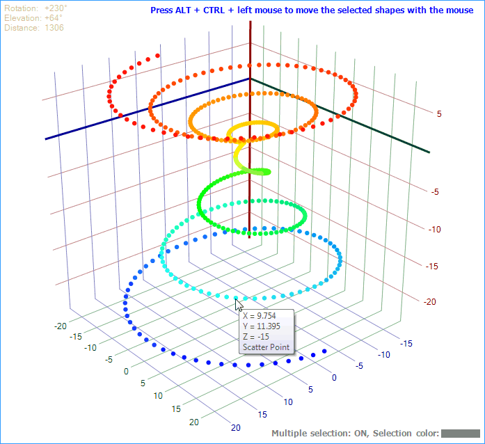
for (double P = -22.0; P < 22.0; P += 0.1)
{
    double d_X = Math.Sin(P) * P;
    double d_Y = Math.Cos(P) * P;
    double d_Z = P;
    if (d_Z > 0.0) d_Z /= 3.0;

    cPoint3D i_Point = new cPoint3D(d_X, d_Y, d_Z, "Scatter Point");
    i_Data.AddShape(i_Point, eScatterShape.Circle, 3, null); 
}

editor3D.Clear();
editor3D.Normalize = eNormalize.Separate;
editor3D.AddRenderData(i_Data);
editor3D.Recalculate(true);


Demo: Scatter Shapes
System.Windows.Forms 3D Editor Control in C#

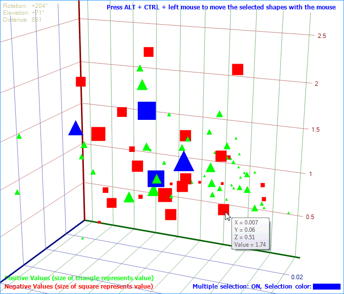
This demo shows negative values as red squares and positive values as green triangles.
Each point in this plot consists of 4 doubles: X,Y,Z and a value.
The value defines the size of the square or triangle while X,Y,Z define the position.
The value is displayed in the tooltip.

4 shapes are selected (blue) and can be moved with the mouse in the 3D space.

 
double[,] d_Values = new double[,]
{
    // Value  X        Y      Z
    {   0.39, 0.0051,  0.133, 0.66 },
    {   0.23, 0.0002,  0.114, 0.87 },
    {   1.46, 0.0007,  0.077, 0.72 },
    {  -1.85, 0.0137,  0.053, 0.87 },
    ......
}

// A ColorScheme is not needed because all points have their own Brush
cScatterData i_Data = new cScatterData(null);

for (int P = 0; P < d_Values.GetLength(0); P++)
{
    double d_Value = d_Values[P, 0];
    int s32_Radius = (int)Math.Abs(d_Value) + 1;

    double X = d_Values[P,1];
    double Y = d_Values[P,2];
    double Z = d_Values[P,3];

    eScatterShape e_Shape = (d_Value < 0) ? eScatterShape.Square : eScatterShape.Triangle;
    Brush         i_Brush = (d_Value < 0) ? Brushes.Red          : Brushes.Lime;

    String s_Tooltip = "Value = " + Editor3D.FormatDouble(d_Value);
    cPoint3D i_Point = new cPoint3D(X, Y, Z, s_Tooltip, d_Value);  
    
    i_Data.AddShape(i_Point, e_Shape, s32_Radius, i_Brush);
}

editor3D.Clear();
editor3D.Normalize = eNormalize.Separate;
editor3D.AddRenderData(i_Data);
editor3D.Recalculate(true);


Demo: Nested Graphs
System.Windows.Forms 3D Editor Control in C#

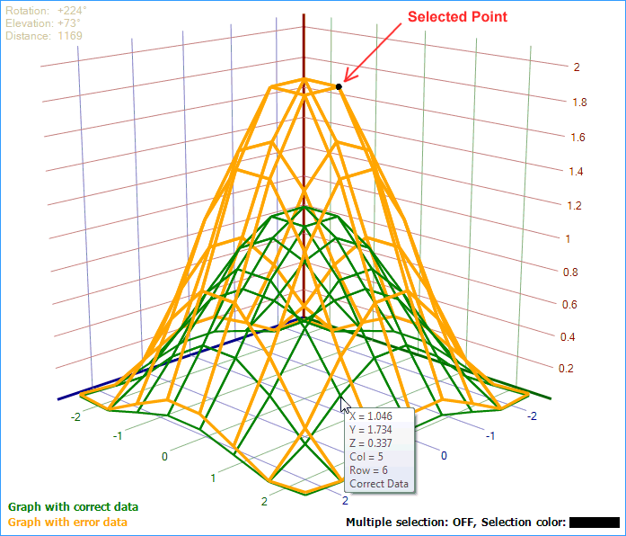
This demo shows how to display 2 graphs at once.
It also shows how to add messages as a legend to the user (bottom left).
This demo demonstrates single point selection. The user can only select one point at a time.

 
const int POINTS = 8;
cSurfaceData i_Data1 = new cSurfaceData(ePolygonMode.Lines, POINTS, POINTS, 
                                        new Pen(Color.Orange, 3), null);
cSurfaceData i_Data2 = new cSurfaceData(ePolygonMode.Lines, POINTS, POINTS, 
                                        new Pen(Color.Green,  2), null);

for (int C=0; C<POINTS; C++)
{
    for (int R=0; R<POINTS; R++)
    {
        double d_X = (C - POINTS / 2.3) / (POINTS / 5.5);
        double d_Y = (R - POINTS / 2.3) / (POINTS / 5.5);
        double d_Radius = Math.Sqrt(d_X * d_X + d_Y * d_Y);
        double d_Z = Math.Cos(d_Radius) + 1.0;

        String  s_Tooltip = String.Format("Col = {0}\nRow = {1}", C, R);
        cPoint3D i_Point1 = new cPoint3D(d_X, d_Y, d_Z,       s_Tooltip + "\nWrong Data");
        cPoint3D i_Point2 = new cPoint3D(d_X, d_Y, d_Z * 0.6, s_Tooltip + "\nCorrect Data");

        i_Data1.SetPointAt(C, R, i_Point1);
        i_Data2.SetPointAt(C, R, i_Point2);
    }
}

cMessgData i_Mesg1 = new cMessgData("Graph with error data",   7,  -7, Color.Orange);
cMessgData i_Mesg2 = new cMessgData("Graph with correct data", 7, -24, Color.Green);

editor3D.Clear();
editor3D.Normalize = eNormalize.MaintainXY;
editor3D.AddRenderData (i_Data1, i_Data2);
editor3D.AddMessageData(i_Mesg1, i_Mesg2);
editor3D.Selection.MultiSelect = false;
editor3D.Selection.Enabled     = true;
editor3D.Recalculate(true);


Demo: Pyramid
System.Windows.Forms 3D Editor Control in C#

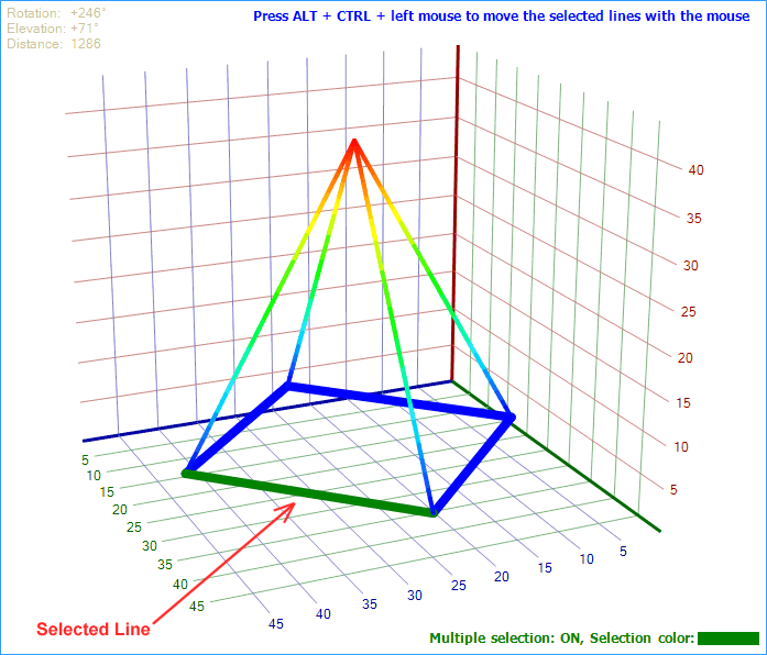
This demo shows a simple 3D object which consists of lines.
Normally lines are drawn in one solid color.
But this demo renders the vertical lines in 50 parts with colors from the rainbow scheme.

 
cLineData i_Data = new cLineData(new cColorScheme(me_ColorScheme));

cPoint3D i_Center  = new cPoint3D(25, 25, 40, "Center");
cPoint3D i_Corner1 = new cPoint3D(25,  5,  5, "Corner 1");
cPoint3D i_Corner2 = new cPoint3D( 5, 25,  5, "Corner 2");
cPoint3D i_Corner3 = new cPoint3D(25, 45,  5, "Corner 3");
cPoint3D i_Corner4 = new cPoint3D(45, 25,  5, "Corner 4");

// Add the 4 vertical lines which are rendered as 50 parts with different colors
cLine3D i_Vert1 = i_Data.AddMultiColorLine(50, i_Center, i_Corner1, 4, null);
cLine3D i_Vert2 = i_Data.AddMultiColorLine(50, i_Center, i_Corner2, 4, null);
cLine3D i_Vert3 = i_Data.AddMultiColorLine(50, i_Center, i_Corner3, 4, null);
cLine3D i_Vert4 = i_Data.AddMultiColorLine(50, i_Center, i_Corner4, 4, null);

// Add the 4 base lines with solid color
cLine3D i_Hor1 = i_Data.AddSolidLine(i_Corner1, i_Corner2, 8, null);
cLine3D i_Hor2 = i_Data.AddSolidLine(i_Corner2, i_Corner3, 8, null);
cLine3D i_Hor3 = i_Data.AddSolidLine(i_Corner3, i_Corner4, 8, null);
cLine3D i_Hor4 = i_Data.AddSolidLine(i_Corner4, i_Corner1, 8, null);

editor3D.Clear();
editor3D.Normalize = eNormalize.MaintainXYZ;
editor3D.AddRenderData(i_Data);
editor3D.Recalculate(true);


Demo: Sphere
System.Windows.Forms 3D Editor Control in C#

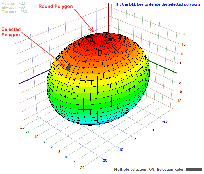
This demo shows another 3D object which is rendered with polygons.
If you have been working with other 3D libraries (WPF, Direct3D) you know that all surfaces must be rendered as triangles.
But my library allows to pass polygons with any amount of corners (minimum 3).
This eliptic sphere contains a round polygon with 50 corners for the top and bottom.

 
The code of this demo is a bit longer.
Have a look into the source code.


Modifying 3D Objects
System.Windows.Forms 3D Editor Control in C#

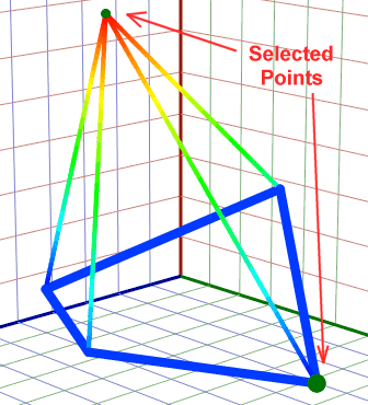
With the checkbox 'Point Selection' in the demo application you can chose if you want to select points or lines.
Press ALT and click a point of the pyramid to select it. A green circle marks it as selected.
Then press ALT + CTRL and drag the selecetd point(s) with the mouse in the 3D space.

All this is handled in the selection callback where you have 100% control over all user actions.

The Selection Callback

 
void DemoPyramid()
{
    .....
    editor3D.Selection.HighlightColor = Color.Green;
    editor3D.Selection.Callback       = OnSelectEvent;
    editor3D.Selection.MultiSelect    = true;
    editor3D.Selection.Enabled        = true;
    .....
}

void OnSelectEvent(eAltEvent e_Event, Keys e_Modifiers, 
                   int s32_DeltaX, int s32_DeltaY, cObject3D i_Object)
{
    bool b_CTRL = (e_Modifiers & Keys.Control) > 0;

    if (e_Event == eAltEvent.MouseDown && !b_CTRL && i_Object != null)
    {
        i_Object.Selected = !i_Object.Selected;
        editor3D.Recalculate(false);
    }
    else if (e_Event == eAltEvent.MouseDrag && b_CTRL)
    {
        cPoint3D i_Project = editor3D.ReverseProject(s32_DeltaX, s32_DeltaY);
        
        foreach (cPoint3D i_Selected in editor3D.Selection.GetSelectedPoints(eSelType.All))
        {
            i_Selected.Move(i_Project.X, i_Project.Y, i_Project.Z);
        }
        editor3D.Recalculate(true);
    }
}

The callback OnSelectEvent() receives several parameters.
Read the comment for function Editor3D.SelectionCallback() where they are explained.
In the first if() the selection of the point/object is toggled when the mouse goes down with ALT key pressed but without CTRL key.
In the else if() the relative movement of the mouse is reverse projected into the 3D space while the user drags the point/object.
This 3D movement in the X,Y,Z directions is then added to the X,Y,Z coordinates of the selected points.

You can write your own callback function which does whatever you like to manipulate the 3D objects.
You can change the coordinates of a 3D object, the color, the shape, the size, the selection status, the tooltip,...
Then you call Recalculate() and the changes appear on the screen.

Pay attention to the status bar which shows all mouse events:

System.Windows.Forms 3D Editor Control in C#


You can assign your own data (a value or instance of your class) to the Tag of any 3D object.
When the callback is called because the user clicks or drags a 3D object you can obtain this data.

 
// Assign an instance of your class to a 3D point:
cPoint3D i_Point = new cPoint3D(....); 
i_Point.Tag = MyClass;

// Retrieve your class instance in the callback
void OnSelectEvent(....., cObject3D i_Object)
{
    MyClass = i_Object.Tag;
}


Deleting 3D Objects
System.Windows.Forms 3D Editor Control in C#

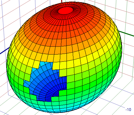
In demo 'Sphere' you can select polygons and delete them by hitting the DEL key.

 
editor3D.KeyDown += new KeyEventHandler(OnEditorKeyDown);

void OnEditorKeyDown(object sender, KeyEventArgs e)
{
    if (e.KeyCode != Keys.Delete)
        return;

    foreach (cObject3D i_Polygon in editor3D.Selection.GetSelectedObjects(eSelType.Polygon))
    {
        editor3D.RemoveObject(i_Polygon);
    }
    editor3D.Recalculate(false);
}


Demo Animation
System.Windows.Forms 3D Editor Control in C#

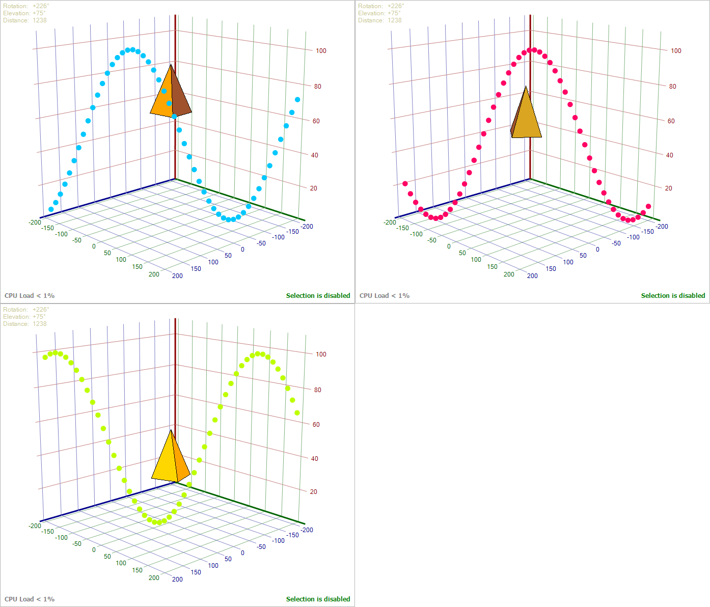
This demo uses a timer which updates 50 scatter circles and a pyramid of 5 polygons.
The sinus is sweeping up and down slowly and changes through all colors of the rainbow.
The pyramid rotates around it's own axis and drifts up and down.

The timer calls this function every 100 ms:

 
void ProcessAnimation()
{
    ms32_AnimationAngle ++;

    // ======== SCATTER =========

    cShape3D[]   i_AllShapes   = mi_SinusData.AllShapes;
    cColorScheme i_ColorScheme = mi_SinusData.ColorScheme;
    double       d_DeltaX      = 400.0 / i_AllShapes.Length;

    double d_X = -200.0;
    for (int S=0; S<i_AllShapes.Length; S++, d_X += d_DeltaX)
    {
        cShape3D i_Shape = i_AllShapes[S];

        i_Shape.Points[0].X =  d_X;
        i_Shape.Points[0].Y = -d_X;
        i_Shape.Points[0].Z = Math.Sin((ms32_AnimationAngle + d_X) / 50.0) * 50.0 + 50.0;

        i_Shape.Brush = i_ColorScheme.GetBrush(ms32_AnimationAngle * 10);
    }

    // ======== PYRAMID =========

    double d_Angle   = ms32_AnimationAngle / 30.0;
    double d_Sinus   = Math.Sin(d_Angle) * 50.0; // -50 ... +50
    double d_Cosinus = Math.Cos(d_Angle) * 50.0; // -50 ... +50
    double d_DeltaZ  = d_Sinus / 2.0;            // -25 ... +25

    // Top
    mi_Pyramid[0].X = -100.0;
    mi_Pyramid[0].Y = -100.0;
    mi_Pyramid[0].Z =   70.0 + d_DeltaZ; 
    // Edge 1
    mi_Pyramid[1].X = -100.0 + d_Sinus;
    mi_Pyramid[1].Y = -100.0 + d_Cosinus;
    mi_Pyramid[1].Z =   40.0 + d_DeltaZ;
    // Edge 2
    mi_Pyramid[2].X = -100.0 + d_Cosinus;
    mi_Pyramid[2].Y = -100.0 - d_Sinus;
    mi_Pyramid[2].Z =   40.0 + d_DeltaZ;
    // Edge 3
    mi_Pyramid[3].X = -100.0 - d_Sinus;
    mi_Pyramid[3].Y = -100.0 - d_Cosinus;
    mi_Pyramid[3].Z =   40.0 + d_DeltaZ;
    // Edge 4
    mi_Pyramid[4].X = -100.0 - d_Cosinus;
    mi_Pyramid[4].Y = -100.0 + d_Sinus;
    mi_Pyramid[4].Z =   40.0 + d_DeltaZ;
}


Tooltip
System.Windows.Forms 3D Editor Control in C#

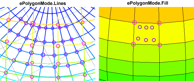
Each polygon corner shows a tooltip when the mouse is over it.
I marked in magenta the locations for the tooltip of the back part of the sphere and in pink of the front part.
If you use ePolygonMode.Fill you will see the tooltip also for corners which are invisible.
This means that in one rectangle on the right screenshot you may see 10 tooltips instead of 4.
Fixing this would require to detect if a corner is covered by a polygon which would extremely decrease the perfomance.
If you find this confusing, I recomend to turn off the tooltip:

 
editor3D.TooltipMode = eTooltip.Off;


Demo: Valentine

And last but not least:
Well, this demo has just been written on 14th february 2021.
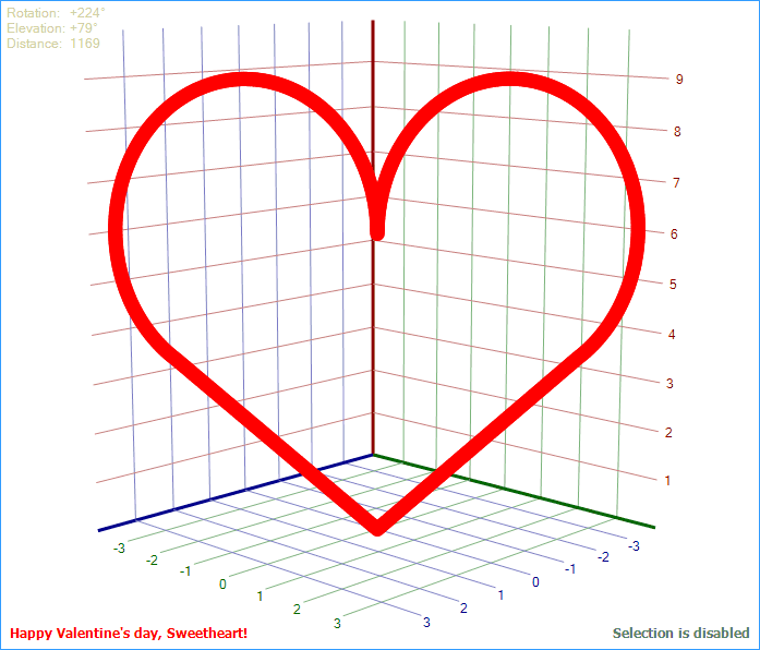
System.Windows.Forms 3D Editor Control in C#


Have fun with my library. Read the plenty of comments in the code!

Elmü

License

This article, along with any associated source code and files, is licensed under The Code Project Open License (CPOL)

경축! 아무것도 안하여 에스천사게임즈가 새로운 모습으로 재오픈 하였습니다.
어린이용이며, 설치가 필요없는 브라우저 게임입니다.
https://s1004games.com

 
Written By
Software Developer (Senior) ElmüSoft
Chile Chile
Software Engineer since 40 years.


Editor3D: C#의 대화형 3D 편집기가 포함된 Windows.Forms 렌더 컨트롤

2023년 9월 2일CPOL9분 읽기
몇 분 안에 애플리케이션에 통합할 수 있는 사용하기 쉬운 3D 컨트롤
System.Windows.Forms 애플리케이션을 위한 즉시 사용 가능한 범용 대화형 3D 편집기 컨트롤입니다. 사용자가 마우스로 수정할 수 있는 3D 데이터를 표시합니다. 컨트롤은 단일 C# 파일로 구성되며 최대 속도에 최적화되어 있습니다.

C#의 System.Windows.Forms 3D 편집기 컨트롤

특징

  • 신규: 컨트롤이 완전히 다시 작성되었습니다(4100줄의 코드, 170kB 파일 크기!)
  • 새로운 기능: 사용자는 ALT 키를 누른 상태에서 마우스로 3D 개체를 선택할 수 있습니다.
  • 새로운 기능: 사용자는 3D 공간에서 마우스를 사용하여 점이나 개체를 이동할 수 있습니다.
  • 새로운 기능: 콜백은 사용자 작업 및 개체 선택을 완벽하게 제어할 수 있습니다.
  • 새로운 기능: 3D 개체를 즉시 추가, 수정 및 제거할 수 있습니다.
  • NEW: 새로운 데모 "애니메이션"은 3D 개체의 속성을 동적으로 변경하는 방법을 보여줍니다.
  • 신규: 3D 편집기가 키보드 포커스를 받으면 테두리 색상이 변경됩니다.
  • NEW: 확대/축소 시 선 너비와 분산점 크기가 조정됩니다.
  • NEW: 모든 움직임에 마우스 왼쪽 또는 가운데 버튼만 사용하도록 구성 가능
  • 3D 개체 그리기를 지원합니다. "피라미드" 및 "구체" 예제가 추가되었습니다.
  • 극도로 최적화된 렌더링 속도
  • 버그 수정: 때때로 Z축이 3D 개체 뒤에 그려지는 경우가 있었습니다.
  • 마우스가 3D 포인트 위에 있을 때 도구 설명 표시
  • 3D 컨트롤 크기 조정 시 3D 개체 크기 조정
  • 동시에 여러 그래프를 표시할 수 있도록 완전히 다시 작성되었습니다.
  • 각 그래프의 개별 색상 구성표
  • 표면 플롯을 그리드로 그릴 수도 있습니다.
  • 사용자 메시지를 컨트롤에 그릴 수 있습니다.
  • 분산형 정사각형 및 삼각형이 추가되었습니다.
  • 스크린샷을 이미지로 복사
  • 프로그래밍 방식으로 Rho, Theta, Phi 설정
  • 산점도 그리기
  • 이제 음수 값도 포함하는 좌표계
  • System.Windows.Forms 애플리케이션을 위한 즉시 사용 가능한 범용 3D 그래프 컨트롤
  • UserControl에서 파생됨
  • 대상: 프레임워크 4(Visual Studio 2010 이상)
  • 3차원 함수 또는 이진 데이터(X, Y, Z 값) 표시
  • 숙련된 프로그래머가 작성한 매우 깨끗하고 재사용 가능한 코드
  • 모든 코드는 1200줄 미만의 단일 C# 파일에 있습니다.
  • 선택적 함수 컴파일러를 사용하면 수식을 문자열로 입력할 수 있습니다.
  • 래스터 선과 라벨이 있는 선택적 좌표계
  • 선택적으로 여러 색상 구성표
  • 사용자는 마우스나 3개의 선택적 트랙바를 사용하여 회전, 높이기 및 확대/축소할 수 있습니다.
  • 마우스 휠을 사용하여 확대/축소할 수도 있지만 3D 그래프에 초점이 있는 경우에만 가능합니다.
  • 전체 코드는 가능한 최대 속도에 최적화되어 있습니다.
  • 선택적 범례는 왼쪽 상단에 사용자에게 현재 회전 각도를 표시합니다.
  • 선택적 범례는 왼쪽 하단 모서리에 축에 대한 사용자 정의 텍스트를 표시합니다.
  • 다각형 사이의 검은색 선을 끌 수 있습니다.
  • 3가지 옵션으로 3D 입력 데이터의 자동 정규화

이 프로젝트를 수행하는 이유는 무엇입니까?

저는 교정 테이블을 표시하는 3D 뷰어가 필요한 ECU 조정 소프트웨어 HUD ECU Hacker를 작성하고 있습니다.
즉시 사용할 수 있는 3D 컨트롤을 인터넷에서 검색했지만 내 필요에 맞는 것을 찾을 수 없었습니다.
Helix Toolkit과 같은 거대한 3D 소프트웨어 프로젝트는 작은 프로젝트에 비해 완전히 과대포장되었습니다(220MB).
0 USD에서 00 USD까지의 상업용 3D 소프트웨어도 옵션이 아닙니다.


WPF 3D 차트(Jianzhong Zhang 제공)

Codeproject에서 WPF 3D 차트를 찾았습니다 .

WPF는 하드웨어 가속을 사용하기 때문에 매우 빠릅니다.
그래픽 프로세서는 삼각형으로 구성되어야 하는 3D 표면을 렌더링할 수 있습니다.
하지만 선을 그리는 것은 어렵습니다. 각 선은 2개의 삼각형으로 정의되어야 합니다.
좌표계에 대한 선이 필요합니다.
3D 표면에 이산 값을 표시하는 선도 필요합니다.
데이터 테이블의 각 값을 3D 개체의 다각형으로 표시하고 싶습니다.
상단의 스크린샷은 22개의 행과 17개의 열이 있는 데이터 테이블의 표현을 보여줍니다.
WPF에서 이것을 구현하는 것이 너무 복잡하다는 것을 알았습니다.
WPF 컨트롤을 Windows.Forms 애플리케이션에 통합하려면 추가 작업을 수행해야 합니다. 이것 좀 봐기사 .

Plot 3D(Michal Brylka 제작)

그러다가 Codeproject에서 Plot 3D를 발견했습니다 .
이것이 내가 찾고 있는 것 이상이지만 코드는 재사용이 불가능하고 많은 문제가 있습니다.

이는 작성자가 한 번도 완료한 적이 없고 버그가 많고 기능이 부족한 Codeproject 또는 Github의 많은 프로젝트 중 하나입니다.
3D 개체를 회전하는 유용한 방법은 없습니다. 회전 각도를 지정하는 대신 완전히 잘못된 설계인 3D 관찰자 좌표를 지정해야 합니다.
이 문제를 해결한 후 회전으로 인해 특정 각도에서 보기 흉한 드로잉 아티팩트가 발생한다는 것을 발견했습니다.
그 이유는 다각형이 올바른 순서로 렌더링되지 않기 때문입니다.
잘못된 프로그래밍으로 인해 코드 성능이 저하됩니다. 예를 들어 OnPaint()그는 매번 100개의 브러시를 생성하고 나중에 폐기합니다.
코드는 수식용으로만 설계되었지만 데이터 테이블에서 수정 값을 할당하는 것은 불가능합니다.

Editor3D(Elmü 제공)

나는 결국 Plot 3D를 처음부터 다시 작성하고, 버그를 수정하고, 누락된 기능을 많이 추가했습니다.
그 결과는 프로젝트에 변경 없이 복사할 수 있고 몇 분 안에 작업할 수 있는 UserControl입니다.
내 컨트롤의 기능은 이미 위에 나열되어 있습니다.
내 코드는 하드웨어 가속을 사용하지 않으므로 표시하는 다각형 수에 따라 그리기 속도가 결정됩니다.
문제 없이 마우스를 사용하여 데모의 3D 개체를 지연 없이 실시간으로 회전하고 높일 수 있습니다.
그러나 훨씬 더 많은 폴리곤을 렌더링하려는 경우에는 분명히 속도가 느려질 것입니다.
내 목적을 위해서는 마우스로 실시간 회전이 가능한 2000개 미만의 다각형이 필요합니다.
ZIP 파일을 다운로드한 다음 이미 컴파일된 EXE 파일을 실행하고 가지고 놀아보면 속도를 확인할 수 있습니다.

데모: 표면 채우기

C#의 System.Windows.Forms 3D 편집기 컨트롤

여기에서는 좌표계가 있는 3D 표면으로 표시된 22x17 값이 있는 테이블의 데이터를 볼 수 있습니다.

 
int[,] s32_Values ​​= new int[,] 
{ 
    { 9059 ,    9634 , 10617 , 11141 , ....., 15368 , 15368 , 15368 , 15368 , 15368 }, // 행 1 
    { 9684 ,   10387 , 11141 , 11796 , ....., 15794 , 15794 , 15794 , 15794 , 15794 }, // 행 2 
    ......... 
    {34669 , 34210 , 33653 , 33096 , ....., 27886 , 26492 , 25167 , 25167 , 25167 }, // 행 21 
    { 34767 , 34210 , 33718 , 33096 , ....., 2798 4, 26492 , 25167 , 25167 , 25167 }   // 행 22 
}; int s32_Cols = s32_Values.GetLength( 0 );
정수

s32_Rows = s32_Values.GetLength( 1 ); 

cColorScheme i_Scheme = new cColorScheme(me_ColorScheme); 
cSurfaceData i_Data = new cSurfaceData(e_Mode, s32_Cols, s32_Rows, Pens.Black, i_Scheme); for ( int C= 0 ; C<i_Data.Cols; C++) 
{ for ( int R= 0 ; R<i_Data.Rows; R++) 
    { int s32_RawValue = s32_Values[C,R]; 더블 d_X = C *   10 . 0 ;
        더블 d_Y = R * 500 . 0 ;
        더블


        d_Z = s32_RawValue / 327 . 68 ; String s_Tooltip = String .Format( " Col = {0}\nRow = {1}\nRaw Value = {2}" , 
                                         C, R, s32_RawValue); 
        cPoint3D i_Point = new cPoint3D(d_X, d_Y, d_Z, s_Tooltip, s32_RawValue); 
        i_Data.SetPointAt(C, R, i_Point); 
    } 
} 
editor3D.Clear(); 
editor3D.Normalize = eNormalize.Separate; 
editor3D.SetAxisLegends( " MAP (kPa)" , " 엔진 속도(rpm)" , " 볼륨 효율(%)" );


editor3D.AddRenderData(i_Data); 

editor3D.Selection.Callback = OnSelectEvent; 
editor3D.Selection.HighlightColor = Color.FromArgb( 90 , 90 , 90 ); // 회색 
editor3D.Selection.MultiSelect = true ; 
editor3D.Selection.Enabled = true ; 
editor3D.Recalculate( true );


이 예에서와 같이 서로 관련되지 않은 X, Y 및 Z에 대해 이산 값을 사용하는 경우 축의 범위가 다르기 때문에 매개 변수를 사용하여 X, Y 및 Z 값이 별도로 정규화 되는지 확인하십시오 .eNormalize.Separate

그리드의 각 점에는 X, Y, Z, 행, 열 및 원시 값 값을 표시하는 도구 설명이 할당되어 있습니다.

이 데모를 사용하면 Alt 키를 누른 상태에서 그리드의 여러 다각형이나 점을 선택할 수 있습니다.
선택한 점의 Z 값은 ALT + CTRL을 누른 상태에서 마우스로 수정할 수 있습니다. 선택과 이동 은
사용자 정의 콜백 에서 처리됩니다 .OnSelectEvent()

데모: 수학 콜백

C#의 System.Windows.Forms 3D 편집기 컨트롤

또는 주어진 X 및 Y 값에서 Z 값을 계산하는 C# 콜백 함수를 작성할 수 있습니다.

 
cColorScheme i_Scheme = new cColorScheme(me_ColorScheme); 
cSurfaceData i_Data = new cSurfaceData(ePolygonMode.Fill, 49 , 33 , Pens.Black, i_Scheme); 

delRendererFunction f_Callback = 대리자 ( double X, double Y) 
{ double r = 0 . 15 * 수학.Sqrt(X * X + Y * Y);
    (r < 1e-10) 인 경우 120을 반환합니다 .
    그렇지 않으면 120 * Math.Sin(r) / r을 반환합니다 . 
}; 
i_Data.ExecuteFunction(f_Callback, 신규
                 
PointF(-120, -80), new PointF( 120 , 80 )); 

editor3D.Clear(); 
editor3D.Normalize = eNormalize.MaintainXYZ; 
editor3D.AddRenderData(i_Data); 
editor3D.Recalculate( true );

변조된 동 함수는 X축에 -120부터 +120까지, Y축에 -80부터 +80까지 표시됩니다.
49개 열과 33개 점 행으로 인해 48개 열과 32개 행의 다각형(총 1536개)이 생성됩니다.

함수를 사용할 때 매개변수를 사용하여 X, Y 및 Z 값 간의 관계가 왜곡되지 않는지 확인하십시오 eNormalize.MaintainXYZ.


데모: 수학 공식

C#의 System.Windows.Forms 3D 편집기 컨트롤

또는 사용자가 런타임에 컴파일될 문자열 수식을 입력하도록 할 수 있습니다.

 
cColorScheme i_Scheme = new cColorScheme(me_ColorScheme); 
cSurfaceData i_Data = new cSurfaceData(ePolygonMode.Fill, 41 , 41 , Pens.Black, i_Scheme); String s_Formula = " 7 * sin(x) * cos(y) / (sqrt(sqrt(x * x + y * y)) + 0.2)" ; 
delRendererFunction f_Function = FunctionCompiler.Compile(s_Formula); 
i_Data.ExecuteFunction(f_Function, new PointF(-7, -7), new PointF( 7 , 7 )); 
editor3D.Clear(); 
editor3D.Normalize = eNormalize.MaintainXYZ; 
editor3D.AddRenderData(i_Data);


editor3D.Recalculate( true );


데모: 산점도

C#의 System.Windows.Forms 3D 편집기 컨트롤


cColorScheme i_Scheme = new cColorScheme(me_ColorScheme); 
cScatterData i_Data = new cScatterData(i_Scheme); for ( double P = -22. 0 ; P < 22 . 0 ; P += 0 . 1 ) 
{ double d_X = Math.Sin(P) * P;
    더블 d_Y = Math.Cos(P) * P;
    더블 d_Z = P;
    if (d_Z > 0 . 0 ) d_Z /= 3 . 0 ; 
    cPoint3D i_Point = 새로운 cPoint3D(d_X, d_Y, d_Z, "


분산점" ); 
    i_Data.AddShape(i_Point, eScatterShape.Circle, 3 , null ); 
} 

editor3D.Clear(); 
editor3D.Normalize = eNormalize.Separate; 
editor3D.AddRenderData(i_Data); 
editor3D.Recalculate( true );


데모: 분산 모양

C#의 System.Windows.Forms 3D 편집기 컨트롤

이 데모에서는 음수 값을 빨간색 사각형으로, 양수 값을 녹색 삼각형으로 표시합니다.
이 플롯의 각 점은 4개의 double(X,Y,Z)과 값으로 구성됩니다.
값은 정사각형이나 삼각형의 크기를 정의하고 X,Y,Z는 위치를 정의합니다.
값이 도구 설명에 표시됩니다.

4개의 도형이 선택되었으며(파란색) 3D 공간에서 마우스로 이동할 수 있습니다.

 
double[,] d_Values ​​= new double[,] 
{ // 값 XYZ 
    {    0 . 39 , 0 . 0051 ,   0 . 133 , 0 . 66 }, 
    {    0 . 23 , 0 . 0002 ,   0 . 114 , 0 . 87 }, 
    {    1 . 46 , 0 . 0007 ,   0 . 077 ,
    0 . 72 }, 
    { -1. 85 , 0 . 0137 ,   0 . 053 , 0 . 87 }, 
    ...... 
} // 모든 포인트에 자체 Brush가 있으므로 ColorScheme이 필요하지 않습니다. 
cScatterData i_Data = new cScatterData( null ); for ( int P = 0 ; P < d_Values.GetLength( 0 ); P++) 
{ double d_Value = d_Values[P, 0];
    int s32_Radius = ( int


    )Math.Abs(d_Value) + 1 ; double X = d_Values[P,1];
    더블 Y = d_Values[P,2];
    double Z = d_Values[P,3]; 
    eScatterShape e_Shape = (d_Value < 0 ) ? eScatterShape.Square : eScatterShape.Triangle; 
    브러시 i_Brush = (d_Value < 0 ) ? 브러쉬.레드 : 브러쉬.라임; String s_Tooltip = " Value = " + Editor3D.FormatDouble(d_Value); 
    cPoint3D i_Point = new cPoint3D(X, Y, Z, s_Tooltip, d_Value);  
    i_Data.AddShape(i_Point, e_Shape, s32_Radius, i_Brush); 
} 
editor3D.Clear();


editor3D.Normalize = eNormalize.Separate; 
editor3D.AddRenderData(i_Data); 
editor3D.Recalculate( true );


데모: 중첩 그래프

C#의 System.Windows.Forms 3D 편집기 컨트롤

이 데모에서는 한 번에 2개의 그래프를 표시하는 방법을 보여줍니다.
또한 사용자에게 메시지를 범례로 추가하는 방법도 보여줍니다(왼쪽 하단).
이 데모에서는 단일 포인트 선택을 보여줍니다. 사용자는 한 번에 한 지점만 선택할 수 있습니다.

 
const  int 포인트 = 8 ; 
cSurfaceData i_Data1 = new cSurfaceData(ePolygonMode.Lines, POINTS, POINTS, 
                                         new Pen(Color.Orange, 3 ), null ); 
cSurfaceData i_Data2 = new cSurfaceData(ePolygonMode.Lines, POINTS, POINTS, 
                                         new Pen(Color.Green,   2 ), null ); for ( int C= 0 ; C<POINTS; C++) 
{ for ( int R= 0 ; R<POINTS; R++)


    { double d_X = (C - POINTS / 2 . 3 ) / (POINTS / 5 . 5 );
        double d_Y = (R - POINTS / 2 . 3 ) / (POINTS / 5 . 5 );
        double d_Radius = Math.Sqrt(d_X * d_X + d_Y * d_Y);
        double d_Z = Math.Cos(d_Radius) + 1 . 0 ; String   s_Tooltip = String .Format( " Col = {0}\nRow = {1}" , C, R); 
        cPoint3D i_Point1 = 신규
        

        cPoint3D(d_X, d_Y, d_Z, s_Tooltip + " \n잘못된 데이터" ); 
        cPoint3D i_Point2 = new cPoint3D(d_X, d_Y, d_Z * 0 . 6 , s_Tooltip + " \n올바른 데이터" ); 

        i_Data1.SetPointAt(C, R, i_Point1); 
        i_Data2.SetPointAt(C, R, i_Point2); 
    } 
} 

cMessgData i_Mesg1 = new cMessgData( " 오류 데이터가 포함된 그래프" ,    7 , -7, Color.Orange); 
cMessgData i_Mesg2 = new cMessgData( " 올바른 데이터가 포함된 그래프" , 7, -24, 색상.녹색); 

editor3D.Clear(); 
editor3D.Normalize = eNormalize.MaintainXY; 
editor3D.AddRenderData(i_Data1, i_Data2); 
editor3D.AddMessageData(i_Mesg1, i_Mesg2); 
editor3D.Selection.MultiSelect = false ; 
editor3D.Selection.Enabled = true ; 
editor3D.Recalculate( true );


데모: 피라미드

C#의 System.Windows.Forms 3D 편집기 컨트롤

이 데모는 선으로 구성된 간단한 3D 개체를 보여줍니다.
일반적으로 선은 단색으로 그려집니다.
하지만 이 데모에서는 무지개 구성표의 색상을 사용하여 수직선을 50개 부분으로 렌더링합니다.

 
cLineData i_Data = new cLineData( new cColorScheme(me_ColorScheme)); 

cPoint3D i_Center = new cPoint3D( 25 , 25 , 40 , " 중심" ); 
cPoint3D i_Corner1 = new cPoint3D( 25 ,   5 ,   5 , " 코너 1" ); 
cPoint3D i_Corner2 = new cPoint3D( 5 , 25 ,   5 , " 코너 2" ); 
cPoint3D i_Corner3 = 새로운 cPoint3D(25 , 45 ,   5 , " 코너 3" ); 
cPoint3D i_Corner4 = new cPoint3D( 45 , 25 ,   5 , " 코너 4" ); // 서로 다른 색상의 50개 부분으로 렌더링되는 4개의 수직선을 추가합니다. 
cLine3D i_Vert1 = i_Data.AddMultiColorLine( 50 , i_Center, i_Corner1, 4 , null ); 
cLine3D i_Vert2 = i_Data.AddMultiColorLine( 50 , i_Center, i_Corner2, 4 , null ); 
cLine3D i_Vert3 = i_Data.AddMultiColorLine(

50 , i_Center, i_Corner3, 4 , null ); 
cLine3D i_Vert4 = i_Data.AddMultiColorLine( 50 , i_Center, i_Corner4, 4 , null ); // 단색으로 4개의 기준선을 추가합니다. 
cLine3D i_Hor1 = i_Data.AddSolidLine(i_Corner1, i_Corner2, 8 , null ); 
cLine3D i_Hor2 = i_Data.AddSolidLine(i_Corner2, i_Corner3, 8 , null ); 
cLine3D i_Hor3 = i_Data.AddSolidLine(i_Corner3, i_Corner4, 8 , null ); 
cLine3D i_Hor4 = i_Data.AddSolidLine(i_Corner4, i_Corner1, 8 ,

 ); 

editor3D.Clear(); 
editor3D.Normalize = eNormalize.MaintainXYZ; 
editor3D.AddRenderData(i_Data); 
editor3D.Recalculate( true );


데모: 구

C#의 System.Windows.Forms 3D 편집기 컨트롤

이 데모는 다각형으로 렌더링되는 또 다른 3D 개체를 보여줍니다.
다른 3D 라이브러리(WPF, Direct3D)로 작업해 본 적이 있다면 모든 표면이 삼각형으로 렌더링되어야 한다는 것을 알고 있을 것입니다.
하지만 내 라이브러리에서는 모서리 수에 관계없이(최소 3개) 다각형을 전달할 수 있습니다.
이 타원 구에는 상단과 하단에 50개의 모서리가 있는 둥근 다각형이 포함되어 있습니다.

 
 데모 의 코드는 조금 더 깁니다 . 소스코드를 살펴 
보세요 .


3D 개체 수정

C#의 System.Windows.Forms 3D 편집기 컨트롤

데모 애플리케이션의 '점 선택' 확인란을 사용하면 점 또는 선을 선택할지 선택할 수 있습니다.
ALT를 누르고 피라미드의 한 점을 클릭하여 선택합니다. 녹색 원은 선택된 것으로 표시됩니다.
그런 다음 ALT + CTRL을 누르고 3D 공간에서 마우스로 선택한 점을 드래그합니다.

이 모든 것은 모든 사용자 작업을 100% 제어할 수 있는 선택 콜백에서 처리됩니다.

선택 콜백

 
void DemoPyramid() 
{ 
    ..... 
    editor3D.Selection.HighlightColor = Color.Green; 
    editor3D.Selection.Callback = OnSelectEvent; 
    editor3D.Selection.MultiSelect = true ; 
    editor3D.Selection.Enabled = true ; 
    ..... 
} void OnSelectEvent(eAltEvent e_Event, Keys e_Modifiers, 
                    int s32_DeltaX, int s32_DeltaY, cObject3D i_Object) 
{ bool b_CTRL = (e_Modifiers & Keys.Control) > 0 ; if (e_Event == eAltEvent.MouseDown && !b_CTRL && i_Object != null


    ) 
    { 
        i_Object.Selected = !i_Object.Selected; 
        editor3D.Recalculate( false ); 
    } else if (e_Event == eAltEvent.MouseDrag && b_CTRL) 
    { 
        cPoint3D i_Project = editor3D.ReverseProject(s32_DeltaX, s32_DeltaY); foreach ( editor3D.Selection.GetSelectedPoints(eSelType.All)  cPoint3D i_Selected ) 
        { 
            i_Selected.Move(i_Project.X, i_Project.Y, i_Project.Z); 
        } 
        editor3D.Recalculate( true ); 
    } 
}


콜백은 OnSelectEvent()여러 매개변수를 받습니다. 설명된
기능에 대한 설명을 읽어보세요 . 처음에는 Ctrl 키 없이 ALT 키를 누른 상태에서 마우스를 아래로 내리면 점/객체 선택이 전환됩니다. 사용자가 점/객체를 드래그하는 동안 마우스의 상대적 움직임이 3D 공간에 역투영됩니다. 그런 다음 X,Y,Z 방향의 3D 이동이 선택한 점의 X,Y,Z 좌표에 추가됩니다.Editor3D.SelectionCallback()
if()
else if()

3D 객체를 조작하기 위해 원하는 모든 작업을 수행하는 콜백 함수를 직접 작성할 수 있습니다.
3D 개체의 좌표, 색상, 모양, 크기, 선택 상태, 툴팁 등을 변경할 수 있습니다.
그런 다음 호출하면 Recalculate()변경 사항이 화면에 나타납니다.

모든 마우스 이벤트를 표시하는 상태 표시줄에 주의하세요.

C#의 System.Windows.Forms 3D 편집기 컨트롤


3D 객체의 태그 에 자신만의 데이터(클래스의 값 또는 인스턴스)를 할당할 수 있습니다 .
사용자가 3D 개체를 클릭하거나 드래그하여 콜백이 호출되면 이 데이터를 얻을 수 있습니다.

 
// 클래스의 인스턴스를 3D 포인트에 할당합니다: 
cPoint3D i_Point = new cPoint3D(....); 
i_Point.Tag = MyClass; // 콜백에서 클래스 인스턴스를 검색합니다. void OnSelectEvent(....., cObject3D i_Object) 
{ 
    MyClass = i_Object.Tag; 
}


3D 개체 삭제

C#의 System.Windows.Forms 3D 편집기 컨트롤

데모 'Sphere'에서는 DEL 키를 눌러 다각형을 선택하고 삭제할 수 있습니다.

 
editor3D.KeyDown += new KeyEventHandler(OnEditorKeyDown); void OnEditorKeyDown( 객체 송신자, KeyEventArgs e) 
{ if (e.KeyCode != Keys.Delete)
         return ; foreach ( editor3D.Selection.GetSelectedObjects(eSelType.Polygon)  cObject3D i_Polygon ) 
    { 
        editor3D.RemoveObject(i_Polygon); 
    } 
    editor3D.Recalculate( false ); 
}


데모 애니메이션

C#의 System.Windows.Forms 3D 편집기 컨트롤

이 데모에서는 50개의 분산원과 5개의 다각형으로 구성된 피라미드를 업데이트하는 타이머를 사용합니다.
부비동은 천천히 위아래로 움직이며 무지개의 모든 색깔을 변화시킵니다.
피라미드는 자체 축을 중심으로 회전하며 위아래로 표류합니다.

타이머는 100ms마다 이 함수를 호출합니다.

 
무효 ProcessAnimation() 
{ 
    ms32_AnimationAngle ++; // ======== SCATTER ========= 
    cShape3D[] i_AllShapes = mi_SinusData.AllShapes; 
    cColorScheme i_ColorScheme = mi_SinusData.ColorScheme; 더블        d_DeltaX = 400 . 0 / i_AllShapes.길이; 더블 d_X = -200. 0 ;
    for ( int S= 0 ; S<i_AllShapes.Length; S++, d_X += d_DeltaX) 
    { 
        cShape3D i_Shape = i_AllShapes[S]; 
        i_Shape.Points[0].X = d_X; 
        i_Shape.Points[0].Y = -d_X;


        i_Shape.Points[0].Z = Math.Sin((ms32_AnimationAngle + d_X) / 50 . 0 ) * 50 . 0 + 50 . 0 ; 

        i_Shape.Brush = i_ColorScheme.GetBrush(ms32_AnimationAngle * 10 ); 
    } // ======== 피라미드 ========= double d_Angle = ms32_AnimationAngle / 30 . 0 ;
    double d_Sinus = Math.Sin(d_Angle) * 50 . 0 ; // -50 ... +50 double d_Cosinus = Math.Cos(d_Angle) * 50 . 0


    ; // -50 ... +50 
    double d_DeltaZ = d_Sinus / 2 . 0 ;            // -25 ... +25 

    // 상단 
    mi_Pyramid[0].X = -100. 0 ; 
    mi_Pyramid[0].Y = -100. 0 ; 
    mi_Pyramid[0].Z =    70 . 0 + d_DeltaZ; 
    // 가장자리 1 
    mi_Pyramid[1].X = -100. 0 + d_부비동; 
    mi_Pyramid[1].Y = -100. 0 + d_코시누스; 
    mi_Pyramid[1].Z =    40 . 0 + d_DeltaZ;
    // 가장자리 2
    mi_Pyramid[2].X = -100. 0 + d_코시누스; 
    mi_Pyramid[2].Y = -100. 0 - d_부비동; 
    mi_Pyramid[2].Z =    40 . 0 + d_DeltaZ;
    // 가장자리 3 
    mi_Pyramid[3].X = -100. 0 - d_부비동; 
    mi_Pyramid[3].Y = -100. 0 - d_코시누스; 
    mi_Pyramid[3].Z =    40 . 0 + d_DeltaZ;
    // 가장자리 4 
    mi_Pyramid[4].X = -100. 0 - d_코시누스; 
    mi_Pyramid[4].Y = -100. 0 + d_부비동; 
    mi_Pyramid[4].Z =    40 . 0+ d_DeltaZ; 
}


툴팁

C#의 System.Windows.Forms 3D 편집기 컨트롤

각 다각형 모서리 위에 마우스를 놓으면 도구 설명이 표시됩니다.
구의 뒷부분 툴팁 위치를 자홍색으로 표시하고 앞부분을 분홍색으로 표시했습니다.
사용하면 ePolygonMode.Fill보이지 않는 모서리에 대한 툴팁도 표시됩니다.
이는 오른쪽 스크린샷의 직사각형 하나에 4개가 아닌 10개의 도구 설명이 표시될 수 있음을 의미합니다.
이를 수정하려면 모서리가 다각형으로 덮여 있는지 감지해야 하므로 성능이 극도로 저하됩니다.
이것이 혼란스럽다면 툴팁을 끄는 것이 좋습니다.

 
editor3D.TooltipMode = eTooltip.Off;


데모: 발렌타인

마지막으로 중요한 점은
이 데모가 2021년 2월 14일에 작성되었다는 것입니다.

C#의 System.Windows.Forms 3D 편집기 컨트롤


내 도서관과 함께 즐거운 시간 보내세요. 코드에 있는 많은 주석을 읽어보세요!

엘무

특허

이 기사는 관련 소스 코드 및 파일과 함께 The Code Project Open License(CPOL) 에 따라 라이센스가 부여됩니다.

 
작성자
소프트웨어 개발자(수석) ElmüSoft
칠레 칠레
40년 경력의 소프트웨어 엔지니어.
 
 
[출처] https://www.codeproject.com/Articles/5293980/Editor3D-A-Windows-Forms-Render-Control-with-inter
 
본 웹사이트는 광고를 포함하고 있습니다.
광고 클릭에서 발생하는 수익금은 모두 웹사이트 서버의 유지 및 관리, 그리고 기술 콘텐츠 향상을 위해 쓰여집니다.
번호 제목 글쓴이 날짜 조회 수
» [C# Apps] Editor3D: A Windows.Forms Render Control with interactive 3D Editor in C# Editor3D: C#의 대화형 3D 편집기가 포함된 Windows.Forms 렌더 컨트롤 file 졸리운_곰 2023.09.03 543
63 [C# app] Pythonnet – .NET Core와 Python의 간단한 결합 : Pythonnet – A Simple Union of .NET Core and Python You’ll Love file 졸리운_곰 2023.03.11 183
62 [C# app] Gidon C# 플러그인 프레임워크에 Python 애플리케이션 포함 : Embedding Python Applications within Gidon C# Plugin Framework file 졸리운_곰 2023.03.07 252
61 [C# App] Gidon - Avalonia 기반 MVVM 플러그인 IoC 컨테이너 : Gidon - Avalonia based MVVM Plugin IoC Container file 졸리운_곰 2023.03.07 168
60 [VS2019] [C#] WinForm에 MySQL 연동하기 file 졸리운_곰 2022.12.25 228
59 [C#] sqlite on C# 예제로 배우는 C# 프로그래밍 file 졸리운_곰 2021.01.30 401
58 Selenium C# Webdriver Tutorial: NUnit Example file 졸리운_곰 2020.01.03 236
57 [C# 인공지능] 유전 알고리즘 : 유전 알고리즘으로 컴퓨터 자동 프로그래밍 AI-Programmer file 졸리운_곰 2019.12.28 391
56 C# 기초로 한글 검색기(초성 포함) 만들기 [Step by Step] file 졸리운_곰 2019.12.11 1832
55 (C#.NET 한글 프로그램 제작) 한글 조립 및 분해 하기 (유니코드 Unicode) file 졸리운_곰 2019.12.11 463
54 C#에서 유니코드를 이용한 한글 자모 분리와 결합 졸리운_곰 2019.12.11 1359
53 [C#] GUID 생성. file 졸리운_곰 2019.02.27 329
52 MetaWeblogAPI C# 코드 샘플 졸리운_곰 2019.02.08 367
51 A Look into the Future - Source Code Generation by the Bots file 졸리운_곰 2019.01.23 315
50 Machine Learning with ML.Net and C#/VB.Net file 졸리운_곰 2018.12.14 585
49 Scientific graphics in C# - [part 2] file 졸리운_곰 2018.12.06 5191
48 Scientific graphics in C# [part 1] file 졸리운_곰 2018.12.06 235
47 Application Trial Maker file 졸리운_곰 2018.11.22 341
46 C# 프로젝트에서 C++ 코드 사용 : Use C++ codes in a C# project — unmanaged C++ solution 졸리운_곰 2018.10.30 375
45 C# 으로 구현하는 간단한 뉴럴네트워크 : Implementing Simple Neural Network in C# file 졸리운_곰 2018.10.30 520
대표 김성준 주소 : 경기 용인 분당수지 U타워 등록번호 : 142-07-27414
통신판매업 신고 : 제2012-용인수지-0185호 출판업 신고 : 수지구청 제 123호 개인정보보호최고책임자 : 김성준 sjkim70@stechstar.com
대표전화 : 010-4589-2193 [fax] 02-6280-1294 COPYRIGHT(C) stechstar.com ALL RIGHTS RESERVED