
- 전체
- C/C++ 일반
- C/C++ 수학
- C/C++ 그래픽
- C/C++ 자료구조
- C/C++ 인공지능
- C/C++ 인터넷
- wxWidget
- GTK+
- UNIX or LINUX programming
- 리눅스 마스터 - 국가공인자격
- VC++/ MFC
- C#/CLI/.NET
- QT/기타UI
- Boost lib
- 오픈소스 C 분석자료
- MSA (마이크로서비스), Docker, kubernetes
- WSL(windows subsystem linux)
C/C++ 그래픽 CONREC : A Contouring Subroutine 등고선 그리기
2018.01.11 16:59
CONREC : A Contouring Subroutine 등고선 그리기
Introduction
This article introduces a straightforward method of contouring some surface represented as a regular triangular mesh.
To do contouring in software you need to describe the data surface and the contour levels you want to have drawn. The software given this information must call the algorithm that calculates the line segments that make up a contour curve and then plot these line segments on whatever graphics device is available. CONREC satisfies the above description, it is relatively simple to implement, very reliable, and does not require sophisticated programming techniques or a high level of mathematics to understand how it works. The input parameters to the CONREC subroutine are as follows :
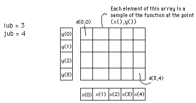 Figure 1 Illustrates some of the above input parameters.
The contouring subroutine CONREC does not assume anything about the device that will be used to plot the contours. It instead expects a user written subroutine called VECOUT. CONREC calls VECOUT with the horizontal and vertical coordinates of the start and end coordinates of a line segment along with the contour level for that line segment. In the simplest case this is very similar the the usual LINE (x1,y1)-(x2,y2) command in BASIC. See the source code listing below. Algorithm
As already mentioned the samples of the three dimensional surface are stored in a two dimensional real array. This rectangular grid is considered four points at a time, namely the rectangle d(i,j), d(i+1,j), d(i,j+1), and d(i+1,j+1). The centre of each rectangle is assigned a value corresponding to the average values of each of the four vertices. Each rectangle is in turn divided into four triangular regions by cutting along the diagonals. Each of these triangular planes may be bisected by horizontal contour plane. The intersection of these two planes is a straight line segment, part of the the contour curve at that contour height. Depending on the value of a contour level with respect to the height at the vertices of a triangle, certain types of contour lines are drawn. The 10 possible cases which may occur are summarised below
In cases a, b, i and j the two planes do not intersect, ie: no line need be drawn. For cases d and h the two planes intersect along an edge of the triangle and therefore line is drawn between the two vertices that lie on the contour level. Case e requires that a line be drawn from the vertex on the contour level to a point on the opposite edge. This point is determined by the intersection of the contour level with the straight line between the other two vertices. Cases c and f are the most common situations where the line is drawn from one edge to another edge of the triangle. The last possibility or case g above has no really satisfactory solution and fortunately will occur rarely with real arithmetic. 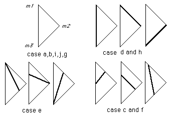 Figure 2 Example
As a simple example consider one triangle with vertices labelled m1,m2 and m3 with heights 0, 2 and 3 respectively 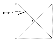 Figure 3 Summary of the possible line orientations.
To calculate where a contour line at a height of 1 should be drawn, it can be seen that this is case f described earlier. Level 1 intersects line segment m1-m2 half the way along and it intersects line segment m1-m3 one third of the way along. A line segment is drawn between these two points. Each rectangular mesh cell is treated this way. Subroutine
In summary, CONREC takes each rectangle of adjacent data points and splits it into 4 triangles after choosing the height at the centre of the rectangle. For each of the triangles the line segment resulting from the intersection with each contour plane. A routine is then called with the starting and stopping coordinates of the line segment.
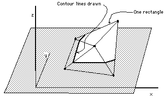 Figure 4
An attempt is made at optimization by checking first to see if there are any contour levels within the present rectangle and second that there are some contour levels within the present triangle. The indices i and j are used to step through each rectangle in turn, k refers to each contour level and m to the four triangles in each rectangle. 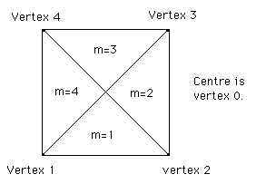 Figure 5 Some of the notation used for identifying the rectangles and triangles in the subroutine. Note that for large arrays the whole data array need not be stored in memory . Since the algorithm is a local one only requiring 4 points at a time, the data for each rectangle could be read from disk as required. Example 1Contour map and the following function  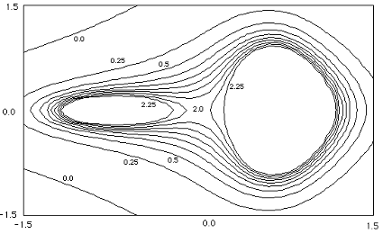 Example 2 Contour map and the following function  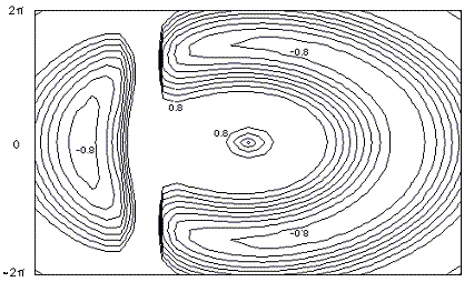
This is a more "real life" example where a C version of CONREC has been used to contour a piece of landscape, the result is given below.  Images from the BYTE magazine version
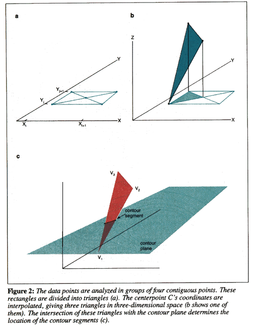
On occasion users have reported gaps in their contour lines, this should of course never happen. There is however a pathological case that all local contouring algorithms suffer from (local meaning that they only use information in the immediate vicinity to determine the contour lines). The problem arises when all four vertices of a grid cell have the same value as the contour level under consideration. There are a number of strategies that can be employed to overcome this special event, the correct way is to consider a larger region in order to join up the contours on either side of the problem cell. CONREC doesn't do this and just leaves the cell without any contour lines thus resulting in a gap. This special case essentially never happens for real values data, it is most commonly associated with integer height datasets. The simplest solution is to offset the contour levels being drawn by a very small amount.
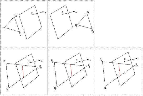
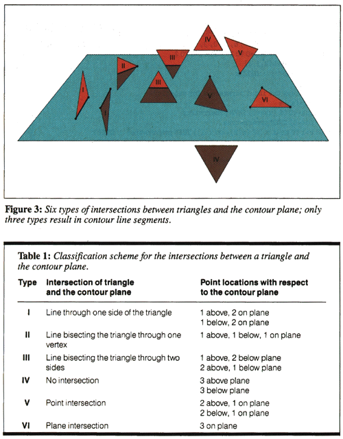
Contouring Facet Based ModelsWritten by Paul BourkeFebruary 1997 This is a short note describing a method for contouring a facet based model, that is, drawing line segments along the intersection of the facets with the contouring plane(s). It is not assumed that the contour plane is parallel to the x-y plane, indeed a totally general contour plane description is employed. The facet is described by its three vertices, P0, P1, P2. The plane is described by its normal n and a point on the plane P. The routine given below returns 0 if there is no intersection of the facet with the contour plane. It returns 2 and the two vertices of the intersection line if the facet does intersect the contour plane. As reflected in the source below, there are 5 basic cases to consider. The first two are when all the vertices of the facet are on one side of the contour plane. The other 3 cases involve finding out which of the three facets is on a side by itself.
 Notes
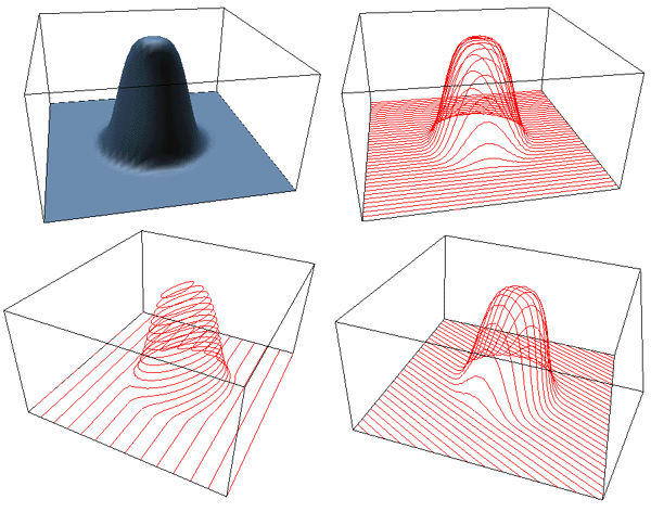
The following examples result from contouring a 2D Gaussian with a range of different orientated contour planes.
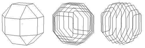
The technique is obviously not limited to traditional contouring of "height surfaces". Closed forms can equally be contoured. The following is a rhombic cubeoctahedron with contours perpendicular to the x axis and y axis.
 The way the above code might be called in order to draw contour lines at multiple levels through a model containing a large number of polygons might be as follows Determine and create the contour plane "n" For each contour level Set the value of p0 appropriately For each polygon in the model Possibly triangulate the polygon if it has more than 3 vertices For each triangular polygon Call ContourFacet() If there were 2 vertices returned draw the line segment End for End for End forFor the simpler case of height contours: source code Practical example Many rapid prototyping machines build models from a number of contour slices, additionally there is a standard file format called stl for that sort of work which consists of simply triangular polygons. Creating instructions for a contour based rapid prototyping machine requires that the triangles representing the objects to be constructed are contoured, possibly along an arbitrary axis. In this example the model is built in miniature in a photonics laboratory (Swinburne University). The model was built in AutoCAD, exported in the STL format, and sliced (129 slices) using software based on the above techniques. The more challenging aspect of this project is dealing with the less than perfect data from AutoCAD, such as the removal of duplicate edges and closing of contour loops. 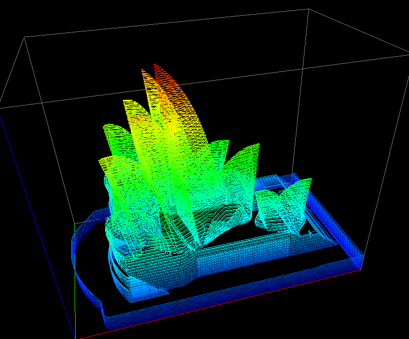
The resulting physical model viewed through a microscope is shown below, the white bar at the bottom is 10 microns (1/100 mm) long making the total length of the model about 0.08mm. 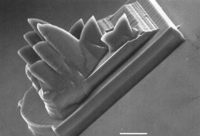
|



CONREC - A Contouring Subroutine.mht Aramini_c.txt autocad.zip ConRec.as conrec.c conrec.cs conrec.go Conrec.java conrec.js conrec.php-x_ conrec.ts conrec_bas.txt conrec_cxx.txt conrec_for.txt conrec_js.txt conrec_vb.txt ConRecVBDemo.zip contours.cpp contours.h coreconrect.dpr cpp.htm-x nncntr_c.txt Render.java test.php-x_ httppaulbourke.netpapersconrec_contour_등고선_그리기_드로잉.zip
광고 클릭에서 발생하는 수익금은 모두 웹사이트 서버의 유지 및 관리, 그리고 기술 콘텐츠 향상을 위해 쓰여집니다.
댓글 0
| 번호 | 제목 | 글쓴이 | 날짜 | 조회 수 |
|---|---|---|---|---|
| 12 |
[MSA] Istio Traffic management
 | 졸리운_곰 | 2021.03.21 | 476 |
| 11 |
[MSA] Istio #4 - Istio 설치와 BookInfo 예제
| 졸리운_곰 | 2021.03.21 | 552 |
| 10 |
[MSA] Istio #3- Istio에 대한 소개
| 졸리운_곰 | 2021.03.21 | 604 |
| 9 |
[MSA] Istio #2 - Envoy proxy
| 졸리운_곰 | 2021.03.21 | 449 |
| 8 |
[MSA] Istio #1 - 마이크로 서비스와 서비스 매쉬
| 졸리운_곰 | 2021.03.21 | 444 |
| 7 |
[MSA][Python] Build and Deploy a REST API Microservice with Python Flask and Docker
| 졸리운_곰 | 2021.03.20 | 405 |
| 6 |
[MSA][KONG gateway] Kong, manage your APIs !
| 졸리운_곰 | 2021.03.20 | 1124 |
| 5 |
[MSA] Monitoring Your Synchronous Python Web Applications Using Prometheus
| 졸리운_곰 | 2021.03.20 | 473 |
| 4 |
[MSA, Docker, Kubernetes] Running Spark on Kubernetes
| 졸리운_곰 | 2021.03.04 | 354 |
| 3 |
[MSA, Docker, Kubernetes] Docker 개념, 관리, 이미지생성까지 한번에!!
| 졸리운_곰 | 2021.03.04 | 702 |
| 2 | 도커 시작하기 7 : Dockerfile을 이용한 이미지 생성 | 졸리운_곰 | 2021.03.04 | 355 |
| 1 |
[MAS, docker, kubernetes] [Container 시리즈] 03. Docker File, Docker Image - 도커파일 및 이미지에 대하여
| 졸리운_곰 | 2021.03.04 | 273 |